17
A supply water connector is welded to the upper part of the heat exchan-
ger, while a return water connector is welded at the bottom, on the back wall. A
discharge connector (G
¾
”) is located on a side wall in the bottom part of the
boiler. It is also used for connection of cooling water (from a water system) when
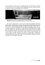
overheat thermal protection – a thermostat valve (a device removing excess heat,
according to Fig. 11 and Fig. 12) is installed. On the side wall of the top of the
boiler there is a connector (G
½
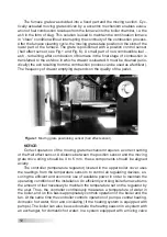
”) for connecting the temperature sensor with a
capillary L=150 mm from thermal protection valve (see fig. 5).
Adjustment feet (does not apply to boilers with power over 25 kW) with the
adjustment range of 30 mm ensure the boiler final alignment versus the floor.
The user is responsible for possible installation of adjustment feet, according to
guidelines provided in this instruction (Fig. 9).
SAS BIO SOLID
automatic boiler with control is delivered with a controller,
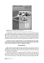
blowing fan, pellet burner (SAS MULTI FLAME), fuel reservoir, ash-box doors,
furnace doors, clean out doors, partitions with refractory ceramic panels. Addi-
tional isolation partitions made of stainless steel protect the furnace door and
clean out door. The boiler body has a thermal insulation made of mineral wool
that has the form of the shell made of powder painted steel sheets with high
resistance to corrosion. The SAS BIO SOLID boiler is equipped with the pellet
burner and fuel reservoir installed on the left (L) or the right (R) side. The burner
and fuel reservoir location should be clearly stated (in the order), as it is not
possible to move them to the other side afterwards.
The digital equipment (control systems) for the SAS BIO SOLID boiler is spe-
cified in the attached operating manual for the temperature controller.
4. SAS BIO SOLID BOILER EQUIPMENT
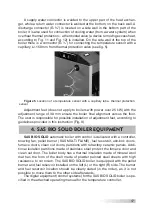
Figure 5
Location of a temperature sensor with a capillary tube– thermal protection
sensor

