2
TABLE OF CONTENTS
page
Declaration of Conformity CE
3
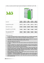
Fact Sheet
4
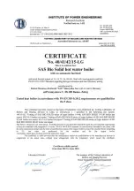
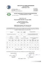
Test certificate for the SAS BIO SOLID water boiler
5-6
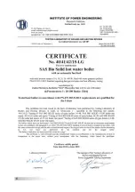
EcoDesign certificate for the SAS BIO SOLID 14kW boiler
7
EURO TOPTEN award
8
1. Preface
9
2. Purpose, boiler operational conditions
9
3. Boiler design and operation
10
4. SAS BIO SOLID boiler equipment
17
5. Technical and operational parameters
18
6. Fuel
23
7. Boiler installation guidelines
24
7.1 Boiler room requirements
25
7.2 Noise and noise reduction methods
26
7.3 Boiler placement
26
7.4. Boiler stack connection
27
7.5. Boiler connection to a heating system
28
7.5.1. Open vented system
29
7.5.2. Sealed system
31
7.6. Boiler connection to a power supply system
37
8. Guidelines for use and operation
38
8.1. Filling with water
38
8.2. Boiler firing and operation
39
8.3. Boiler cleaning
41
8.4. End of burning
43
9. Conditions for safe operation
44
10. Operation and maintenance of the feeder and burner
45
11. Statuses of incorrect boiler work
46
12. Protective devices
48
13. Delivery terms and conditions
51
14. Boiler disposal
52
15. Warranty terms and conditions
55
Warranty card
55
LIST OF FIGURES AND TABLES
Table
. 1 SAS BIO SOLID boiler equipment
18
Table
. 2 Technical and operational parameters for the
SAS BIO SOLID 14-f 48 kW boiler
19
Table
. 3 Basic parameters of pellets intended for SAS BIO SOLID boilers
23
Figure
. 1 Moving grate positioning sensor (hall effect sensor)
12
Figure
. 2 Connection terminal strip supplying control equipment
13
Figure
. 3 Module controlling burner operation
14
Figure
. 4 The flue gas temperature sensor mounted in flue pipe
15
Figure
. 5 Location of the temperature sensor with a capillary tube
– thermal protection sensor
17
Figure
. 6 Diagram of SAS BIO SOLID boiler design with heat output of 14 -f 48 kW
20
Figure
. 7 Diagram of SAS MULTI FLAME burner design - side view, sectional view
21
Figure
. 8 Diagram of SAS MULTI FLAME burner design - upper view
22
Figure
. 9 Installation of adjustment feet in SAS BIO SOLID boiler
27
Figure
. 10 General connection diagram - an open vented system with a four-way valve
32
Figure
. 11 General connection diagram - an open vented system with a plate exchanger
33
Figure
. 12 General connection diagram - sealed system
34
Figure
. 13 Flue gas turbulator
42
Figure
. 14 The location of the STB safety temperature limiter and temperature sensor
49

