background image

23

6. FUEL

* In particular, during fuel loading or replenishment attention should be paid to presence of wood pieces, stones or unde-
sirable objects that may block the feeder mechanism.

Seamless operation of the SAS BIO SOLID boiler with SAS MULTI FLAME 

pellet burner depends on the application of the respective fuel. 

The fuel for SAS 

BIO SOLID boilers is the biomass is in the form of pressed granules of pellet-

-type wood, acc. to EN 14961-2 Class C1 or by PN-EN ISO 17225-2:2014-07p 

class A1.

 Do not use fuel with granulation thicker than specified*, since such fuel 

may hinder the operation of the feeder and lead to its damage. SAS BIO SOLID 
boiler equipped with automatic pellet burner is not a device for the combustion 
of fossil fuels.

NOTE! The use of other fuels than recommended by the manufacturer 

may cause damage to the burner, leading to loss of warranty on the burner.

It is forbidden to burn plastic materials; this may result in damage to the fur-

nace. Contamination of the heat exchanger surface leads to reduced boiler effi-
ciency and deterioration in the burning process. It is forbidden to use flammable 
materials (such as petrol, kerosene, or solvents) for boiler firing, as this may result 
in a fire or explosion.

Boilers fired with biogenic class „C1” fuel according to Chapter 1 of PN-EN 

303-5:2012 standard.

No.

Parameter

Unit

Scope

1

Diameter

mm

6 - 8

2

Length

mm

5 - 35

3

Bulk density

kg/m

3

 600

4

Calorific value

MJ/kg

16,5 - 19

5

Abrasiveness

%

 2,5

6

Ash content

%

 0,5

7

Sulphur content

%

 0,03

8

Nitrogen content

%

 0,3

9

Chlorine content

%

 0,02

10

Water content

%

 12

Table 3 

Basic parameters of pellets intended for SAS BIO SOLID boilers:

The density determines the durability of fuel, abrasiveness, pulp formation and 

in result too low density may cause jamming of locking mechanism of the feeder.

It is forbidden to use fuel with a humidity higher than specified in the table 

above. Fuel with high humidity can impede the combustion process and cause 
damage to the auger feeder, feeder tubes, fuel reservoir (premature corrosion).

Summary of Contents for BIO SOLID 14

Page 1: ......

Page 2: ...arranty terms and conditions 55 Warranty card 55 LIST OF FIGURES AND TABLES Table 1 SAS BIO SOLID boiler equipment 18 Table 2 Technical and operational parameters for the SAS BIO SOLID 14 f 48 kW boil...

Page 3: ...with the provisions of Directive 2006 42 EC The Ordinance Of The Minister Of The Economy Official Journal No 199 2008 item 1228 MD Machinery Directive Directive 2004 108 EC Official Journal No 82 200...

Page 4: ...aximum working temperature declared i e 85 C 5 Flue gases emitted from an obstructed stack are hazardous The stack and the connector should be kept clean they should be cleaned according to the instru...

Page 5: ...5...

Page 6: ...6...

Page 7: ...7...

Page 8: ...8...

Page 9: ...ter central heating systems open close system with gravitational or forced water flow secured according to current local or EU regulations PN EN 12828 A1 2014 05 Heating installations in buildings De...

Page 10: ...programmed for combustion of the solid fuel in automatic mode The fuel is bio mass in the form of wood granules wood pellets with parameters defined by EN 14961 2 or PN EN ISO 17225 2 2014 07p Basic b...

Page 11: ...ed by a stream of air coming from the air duct After reaching the preset temperature the automatic fuel ignition and fire support system enables the boiler the possibi lity of efficient operation even...

Page 12: ...t operation of the moving grate mechanism requires a correct setting of the Hall effect sensor A distance between the position sensor and the moving grate drive string should be 3 to 5 mm these compon...

Page 13: ...temperature sensor The co operation between the controller Fig 6 item 39 of the feeder SAS MULTI FLAME type the master boiler controller Fig 6 item 28 is possible thanks to the wired RS communication...

Page 14: ...ly control activi ties must be performed to prevent emergency situations BOILER DESIGN With the boiler structure based on three pass layout of a flue gas duct in the exchanger with ceramic panels flue...

Page 15: ...for closing systems for doors and a fuel tank cover Non flammable insulating materials were installed to reduce heat losses and secure against excessive increase in a temperature of external boiler su...

Page 16: ...a few seconds When the fuel reservoir cover is closed the operation is resumed Inside the cover there is an information for the user about the presence and operation of the limit switch reservoir cove...

Page 17: ...ided in this instruction Fig 9 SAS BIO SOLID automatic boiler with control is delivered with a controller blowing fan pellet burner SAS MULTI FLAME fuel reservoir ash box doors furnace doors clean out...

Page 18: ...made of stainless steel protecting the cleanout door pieces 1 12 The set of refractory ceramic panels rear front sides horizontal partitions pieces 1 13 The set of refractory ceramic panels boiler sid...

Page 19: ...230V 50Hz 21 Power consumption W up to 220 600 on ignition 22 Noise level by PN EN 15036 1 2006 dB 65 dB A 23 Basic boiler dimensions Amps mm 1230 1270 1270 1290 1410 A1 mm 290 290 290 305 330 B mm 9...

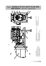
Page 20: ...side 11 Ceramic panels rear front 12 Ceramic shelves 13 Furnace doors 14 Protective partition 15 Clean out hatch door 16 STB safety temperature limiter 17 Power strip 18 Flue gas turbulator 19 Flue g...

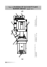
Page 21: ...s separated by the transfer duct 4 Fuel feeder temperature sensor 5 Moving grate drive motor 6 Feeder supporting foot 7 Hall effect sensor moving grate positioning sensor 8 Thermally insulated air duc...

Page 22: ...BURNER DESIGN upper view 15 Moving grates number depends on the burner power 16 Sealing cord 17 Burner mounting plate 18 Blower fan 19 Gear motor for the feeder 20 Feeder drive unit 21 Housing of the...

Page 23: ...terials this may result in damage to the fur nace Contamination of the heat exchanger surface leads to reduced boiler effi ciency and deterioration in the burning process It is forbidden to use flamma...

Page 24: ...chimney degree exchanger contamination inside and outside temperature of the heated building building insulation NOTICE The fuel tank should be loaded with fuel free of water and exces sive quantitie...

Page 25: ...n the back part of the room a device controlling air flow should be installed in a supply aperture or duct however it sho uld not reduce the cross section to less than 1 5 no supply ventilation or its...

Page 26: ...system damping connectors vibration compensator e g EFAR DANFOSS etc can be installed The boiler should be set according to guidelines provi ded in chapter 7 3 Setting a boiler 7 3 SETTING A BOILER T...

Page 27: ...y connected to the stack with a smoke connection in form of a steel pipe 3 mm thick of a thermal resistance of 400 C and of a diameter allowing its tight connection to the flue outlet and inserting in...

Page 28: ...emperature of exhaust gas at the nominal thermal power bo iler can cause pollution wet deposition of soot insufficient chimney flow This may result in moisture accumulation and corrosion of masonry ch...

Page 29: ...ed with the following components a circulatory pump and a domestic hot water temperature sensor connected to a supply terminal strip on the boiler side The system should be constructed by a qualified...

Page 30: ...ceptable as this may damage the sewage system When the temperature in the sensor environment drops below 95 C the re lief valve is closed automatically and water flow from the overflow vessel is stop...

Page 31: ...precipita ting deposits may affect temperature indications and prolong the time needed to open a valve protecting against overheating For correct operation of the thermostat valve markings showing a c...

Page 32: ...tank 7 four way valve 8 circulatory pump of a central heating system 9 central heating system RW expansion pipe RB pressure relief pipe RO venting pipe RP overflow pipe RS signalling pipe Figure 10 Ge...

Page 33: ...tank 15 circulatory pump of an open vented system 16 plate heat exchanger 17 circulatory pump of a sealed system RW expansion pipe RB pressure relief pipe RO venting pipe RP overflow pipe RS signallin...

Page 34: ...tube 4 cut off ball valve 5 sump strainer 6 thermal protection device e g SYR type 5067 protecting the system against overheating 7 differential pressure control valve 8 circulatory pump of a domesti...

Page 35: ...e cold water may flow from the supply pipe cooling down the boiler When lowering the temperature of the boiler to 94o C the discharge valve is closed With thermally controlled filling valve and temper...

Page 36: ...gs Design for water based heating systems PN EN 303 5 Minister of Infrastructure Regulation concerning technical conditions that should be met by buildings and their setting of 12 April 2002 Jour nal...

Page 37: ...devices working with it ope rate under voltage of 230 V therefore all connections can only be made by a person having required qualifications Polish Electricians Association licence up to 1kV All work...

Page 38: ...grees free oxygen content 0 1 mg O2 l Temporary hardness caused by hydrogen carbonates that are thermally unstable and when heated are transformed into water insoluble carbonates deposited as lime sca...

Page 39: ...erature When a supply ventilation is not installed this may result in generation of large quantities of flammable highly explosive gases a risk of damage to the flue pipe NOTICE Both the fuel reservoi...

Page 40: ...firing process on the controller ceramic burner In the boiler automatic mode a set temperature boiler water temperature value must be set on a con troller along with the operating time and intervals i...

Page 41: ...on if the heating system is equipped with pumps Regularly at least once a day open the furnace door and check the flame condition furnace appearance When any deviations are noticed adjust the bo iler...

Page 42: ...ust slag At the factory the boiler was equipped with a set of ceramic sealant see inspec tion clean our doors holes Regular inspection of the sealant condition is recommen ded and its replacement when...

Page 43: ...ir chamber see fig 7 item14 possibly shutoff the boiler and clean the furnace the pellet burner When the boiler is equipped with a flue gas temperature sensor its surfa ce must be cleaned regularly to...

Page 44: ...rflow pipes is very dangerous as it may result in the boiler damage it is forbidden to fire the boiler using flammable materials such as petrol kerosene or solvents as this may result in explosion or...

Page 45: ...of air nozzles and patency of air outlets 7 Periodically clean dust and residues of fuel or ash from the feeder 8 Regularly clean the motor casing using a dry cloth 9 Do not use any solvents for clea...

Page 46: ...patency and parameters see a table specifying appropriate chimney hight and cross section for a given boiler output check whether the chimney does not end below the highest roof ridge contamination of...

Page 47: ...eating system and the boiler e g due to incorrect filling of the system and the boiler with water boiler warming up i e maintaining the temperature above 70 C for longer time until air bubbles are com...

Page 48: ...g mes sage Temperature does not increase When the encoder is pressed the alarm is switched off The controller returns to the last set operational mode AUTOMATED SENSOR MONITORING When the central heat...

Page 49: ...90 to 100 C The equipment cannot be restarted automatically even when the temperature is lowered The user must switch them on resetting the sensor with the button after the temperature of the boiler...

Page 50: ...r is additionally secured against flashback to the fuel tank hop per The boiler is equipped with a feeder pipe sensor measuring temperature near the fuel tank When the temperature increases significan...

Page 51: ...ed in the sealed system e g SYR type 5067 When the boiler is overheated jacket temperature above 95 C the thermal pro tection valve installed on the boiler is opened the water supplied from the water...

Page 52: ...to a relevant waste collection entity The waste collection place should be specified by relevant municipal or commune services 15 WARRANTY TERMS AND CONDITIONS 1 The manufacturer grants to the Buyer a...

Page 53: ...ensures free of charge repairs of the subject matter of the agreement within 14 days of a date of notification 11 A defect covered by a warranty repair should be notified immediately when that defect...

Page 54: ...ress and product moder nisation These changes may not be included in this operation and mainte nance documentation while the basic described features of the product will be maintained All issues and q...

Page 55: ...period of 60 months on low temperature boiler SAS BIO SOLID boiler is given in accordance with the technical documentation Boiler no Thermal power Heating surface Year of manufacture Signature and sta...

Page 56: ......

Reviews: