GB
14
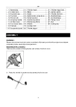
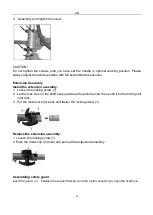
3. Assembly and tighten the screw.
CAUTION!
Do not tighten the screws until you have set the handle in optimal working position. Please
always adjust the handle position with full assembled accessories.
Extension Assembly
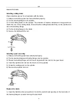
Install the extension assembly:
1. Loosen the locking screw (1),
2. Let the lock hole on the shaft keep upside as the picture show then push it to the driving unit
until click,
3. Put the metal cover(3) back and fasten the locking screw (1).
Remove the extension assembly:
1. Loosen the locking screw (1).
2. Push the metal clip (2) down and pull out the extension assembly.
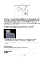
Assembling safety guard
Insert the guard
(
a
)
between the support frame(c) and the metal connector (b), align the fixed hole.
Summary of Contents for RM-MT330-2
Page 12: ...FR 12 LISTE DES PRINCIPAUX ELEMENTS ...
Page 31: ......
Page 43: ...GB 12 LIST OF MAIN PART ...

