User’s manual
18
VI.1.
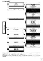
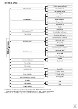
PID coefficient
NOTE
This submenu concerns CH boiler operation with PID control and t is available only when
zPID control is active.
VI.1.a)
CH boiler power coefficient
CH boiler power coefficient
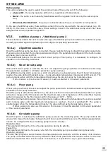
serves to control the feeder and fan operation at the same time. 100% is the
default value but it may be adjusted within the range of 50-110%. Once a change is introduced, the
upper limit of zPID parameters is moved (operation/pause time of the feeder and blow force). The lower
limit of parameters remains unchanged.
VI.1.b)
Fan correction bottom / Fan correction top
This function is used to adjust the fan speed. If the blow force is too low/high, the coefficient should be
adequately increased/decreased in order to ensure efficiency.
The user may adjust the fan speed for both minimum and maximum CH boiler power indicated by zPID
(
Fan correction bottom
and
Fan correction bottom
parameters).
VI.2.
PID supervision
NOTE
This submenu concerns CH boiler operation with PID control and t is available only when zPID
control is active.
In this function the user configures the combustion
parameters for the situation when the CH boiler
temperature exceeds the pre-set value by 5°C. If
Damping mode
function is selected, the damping
process is initiated when the pre-set temperature value is exceeded by 5°C. Once the process is
completed, the controller constantly monitors the CH boiler temperature. If it drops by a pre-defined
vale, the fire-up process is initiated again.
NOTE
Damping mode concerns only pellet-fired CH boilers controlled with the use of an additional
ST-66P module.
The remaining options should be configured if the user does not want the CH boiler to be damped when
the controller enters supervision mode. The user sets fuel feeding time, feeding pause as well as fan
operation and pause time during fuel feeding (blow-by gear)
The function is deactivated automatically when the CH temperature drops to the pre-set value.
VI.3.
Buffer parameters
NOTE
Function available only when ST-66B module is used.
These parameters enable the user to configure controller operation settings in the case of heating
systems with a buffer.
VI.3.a)
Buffer
Once buffer function is activated (by selecting ON) , CH pump serves as pump of the buffer in which two
sensors are installed: upper (C1) and lower (C2). The pump remains active until the pre-set temperature
of buffer bottom is reached. When the temperature drops below the pre-set buffer top temperature, the
pump is activated again.
VI.3.b)
DHW function
If buffer is used in the heating system, it is necessary to specify how the water tank is connected:
- from CH boiler – the heating system in which DHW tank is connected directly to the CH boiler (a
separate circuit).
- from buffer – the heating system in which DHW tank is built in or connected to the buffer.
Summary of Contents for ST-550 zPID
Page 1: ......
Page 6: ...User s manual 6...
Page 7: ...ST 550 zPID 7...
Page 30: ...User s manual 30...
Page 36: ...User s manual 36...

