- 2 -
I
NSTALL THE THERMOSTAT
ATTACH THERMOSTAT BASE TO WALL
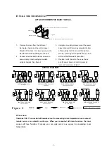
1.. Remove 2 screws from the bottom of
thermostat. Gently pull the control panel
straight off the base. Forcing or prying on the
thermostat will cause damage to the unit.
2. Connect wires beneath terminal screws on
power supply module using appropriate
wiring schematic. See figure 4
3. Using two mounting screws mount the power
base to the wall. Place a level against bottom
of base, adjust until level, and then tighten
screws. (Leveling is for appearance only and
will not affect thermostat operation.)
4. Replace control panel on the power base
and fix power base and control panel by
removed two screws in item 1
WIRING DIAGRAM
Va
lv
e
N
L
3
ME
HI
5
7 8
HE
AT ON
6
Fan
4
LO
9
1
2
11
10
NTC
100K
S
E
NSOR
Va
lv
e
N
L
3
ME
HI
5
7 8
CO
O
L
O
N
6
Fan
4
LO
9
1
2
11
10
NTC
100K
SE
NSOR
SENSOR
100K
NTC
10 11
2
1
9
LO
4
Fan
6
HE
AT ON
HE
AT
OF
F
8
7
5
HI
ME
3
L
N
2
1
9
LO
4
Fan
6
CO
O
L
O
N
8
7
COO
L
OF
F
5
HI
ME
3
L
N
SEN
S
OR
100K
NTC
10 11
HEAT ONLY ,2 PIPE,3 WIRE
SPDT VALVE FAN COIL
UNIT SYSTEM
HEAT ONLY, 2 PIPE, 2 WIRE
SPST VALVE FAN COIL
UNIT SYSTEM
SEN
S
OR
100K
NTC
10 11
2
1
9
HEAT/COOL 4 PIPE , 3 WIRE
SPDT VALVE, FAN COIL
SYSTEM,
LO
4
Fan
6
CO
O
L
O
N
HE
AT
O
N
HE
AT
O
F
F
8
7
C
OOL
OF
F
5
HI
ME
3
L
N
Va
lv
e
Va
lv
e
N
L
3
ME
HI
5
7 8
HE
AT
O
N
CO
O
L
O
N
6
Fan
4
LO
9
1
2
11
10
NTC
100K
S
E
NS
OR
HEAT/COOL, 4 PIPE, 2 WIRE
SPST VALVE FAN COIL UNIT
SYSTEM
N
L
3
ME
HI
5
7 8
OF
F
ON
6
Fan
4
LO
9
1
2
11
10
NTC
100K
SE
NSOR
HEAT OR COOL, 2 PIPE, 3
WIRE SPDT VALVE FAN
COIL UNIT SYSTEM
SEN
S
OR
100K
NTC
10 11
2
1
9
LO
4
Fan
6
ON
8
7
5
HI
ME
3
L
N
Va
lv
e
HEAT OR COOL, 2 PIPE, 2
WIRE SPST VALVE FAN
COIL UNIT SYSTEM
COOL ONLY, 2 PIPE, 3 WIRE
SPDT VALVE FAN COIL
UNIT SYSTEM
COOL ONLY, 2 PIPE, 2 WIRE
SPSTVALVE FAN COIL UNIT
SYSTEM
Figure 4
Valve
风机
Fan
:
FAN
:2
WIRE VALVE
3
WIRE VALVE
NOTE
POWER:100-240VAC 50/60HZ
Please note:
Terminals 10 & 11 connected with remote sensor for measuring room temperature. Inner sensor &
remote sensor can automatic exchange . When you connected with remote sensor, the inner
sensor will lose function. It means you can only select one sensor for measuring room
temperature.
Screw for mounting thermostat to conduit box
Figure 3
Screw for fixing control panel and power base
Panel base
Control panel


