background image


8


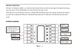
* NOTE:Jumper wire required to use a single Aux Heat for both AUX Heating and Emergency 

Heating. NOTE** When presented with 24VAC on the “L” terminal, the Alarm Icon will flash on 

the display.   


CHECK THERMOSTAT OPERATION 

If at any time during testing your system does not operate properly, contact a qualified service person.     

Heating system 

Turn on power to the system.    Fan Operation Move the system switch to the OFF position. If your system does not 

have a “G” (Fan) terminal connection, skip to the Heating System.     

1.Move the fan switch to the ON position. The blower should begin to operate.   

2.Move the fan switch to the AUTO position. The blower should stop immediately. 

3.Move the SYSTEM switch to the HEAT position. If the auxiliary heating system has a standing pilot, be sure to 

light it.     


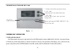
When the (FA)st heating cycle rate is selected in the configuration menu, (see configuration   

menu item 2), the thermostat will call for heat at 0.5ºF (0.5ºC) below set-point, and turn off at set point. When the 

(SL)ow heating cycle rate is selected, the thermostat will call for heat at 1.5ºF (1.5ºC) below set-point, and turn off at 

Summary of Contents for T21HTW-0

Page 1: ...1 T21HTW 0 OPERATING INSTRUCTION...

Page 2: ...to 90 F 7 C to 32 C Accuracy 1 F or 0 5 C Dimensions 6 0 W X 4 7 H X 1 1 D Color White FEATURES Large LCD display with backlight continuous backlight option Simultaneous heat and cool set point storag...

Page 3: ...ead all of the information in this manual before installing this thermostat Use a professional contractor to install this thermostat This is a 24VAC low voltage thermostat DO NOT INSTALL ON VOLTAGES H...

Page 4: ...ate circuit breaker to the OFF position before removing the existing thermostat 2 Turn off power to the heating and cooling system by removing the fuse or switching the appropriate circuit breaker off...

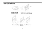
Page 5: ...THERMOSTAT Push the button to open thermostat front cover Installing the screws in the base cover into the junction box and finish wiring Close the lid then fitting the 2AA Battery push up the slide c...

Page 6: ...ermostat base against the wall where you plan to mount it Be sure the wires will feed through the wire opening in the base of the thermostat 6 Mark the placement of the mounting holes 7 Move the base...

Page 7: ...by snapping it in place 13 Turn on power to the system at the main service panel 14 Test thermostat operation as described in the following section Fan operation switch Read the following information...

Page 8: ...isplay is flashing it indicates that the batteries need to be replaced When the thermostat is powered only by battery the battery icon will flash for approximately 2 months before the batteries are ex...

Page 9: ...G Fan terminal connection skip to the Heating System 1 Move the fan switch to the ON position The blower should begin to operate 2 Move the fan switch to the AUTO position The blower should stop imme...

Page 10: ...y damage if the outdoor temperature is below 50 F 10 C DO NOT operate the cooling system 1 Move the SYSTEM switch to the COOL position 2 When the FA st cooling cycle rate is selected in the configurat...

Page 11: ...cted in the configuration menu See configuration menu item 2 the thermostat will call for Emergency heat at 0 5 F below the set point and turn off at set point When the SL ow heating cycle is selected...

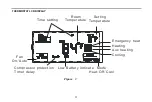
Page 12: ...MOSTAT LCD DISPLAY Setting Temperature Low Battery indicate Compressor protection Timer delay Fan On Auto Room Temperature Mode Heat Off Cool Cooling Heating Time setting Emergency heat Aux heating Fi...

Page 13: ...ou want to maintain is shown on the right side of the display If you want to turn the system off just move the SYSTEM switch to the OFF position and the FAN switch to the AUTO position 1 Raises or low...

Page 14: ...Filter review Move the SYSTEM switch to the HEAT or COOL position then press and hold the and buttons for 5 seconds to review filter running days To exit the review menu press the or buttons one time...

Page 15: ...0 5 C differential and SL cycles the system at 1 5 F 1 5 C 3 Select display backlight The display backlight improves display contrast in low lighting conditions Select 1 for NO backlight display Sele...

Page 16: ...at The current or adjusted room temperature will be displayed on the display 7 Select compressor lockout delay 0 1 2 3 4 5 To protect the compressor from short cycling you can select compressor off ti...

Page 17: ...xt menu item Use the button to select each user setting To exit the configuration menu and return to normal operation move the SYSTEM switch to the HEAT or COOL position If no buttons are pressed with...

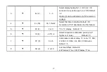
Page 18: ...er time in months Default 00 A selection of 00 deactivates the filter feature 5 FC F F or C F or C display Default F 6 CL 0 4 TO 4 Select temperature calibration point up to 4 higher or 4 lower Defaul...

Page 19: ...18 CUSTOMER ASSISTANCE After reading this guide if you have any question about the operation of your thermostat please contact your installer or Energy Utility company or service provider...

Page 20: ...19...
Reviews: