113
US
Operating Manual SATAjet 4600 B RP/HVLP
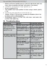
• Make sure that the spindle pick-up is free of material and paint resi-
dues, remove residues and clean with solvent, if necessary
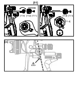
2. Installation and position of new spindle [a, b]
• Screw in spindle [11-3]
•
Turn spindle nut [11-3] to position 6 o’clock using a wrench (size 6)
[11-4]
3. Positioning and assembly of control knob [c]
•
Position of knob [11-2] has to be according to illustration (line in the
knob has to be in vertical position)
•
Hand-tighten screw [11-1] (Torx T20) in the knob - hold knob in the
position while tightening
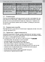
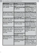
10. Troubleshooting
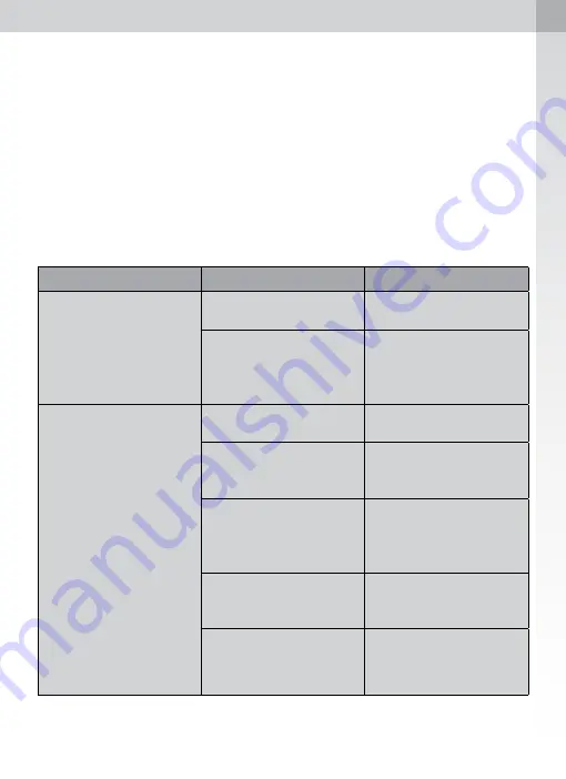
Malfunction
Cause
Corrective action
Fluttering/spitting
spray fan or air bub-
bles appearing in the
gravity flow cup
Fluid tip has not been
properly tightened
Tighten fluid tip
[2-1]
with universal spanner
Air distribution ring is
damaged or clogged.
Replace air distribu-
tion ring, as it will be
damaged during disas-
sembly
Air bubbles appearing
in the gravity flow cup
Loose air cap
Tighten air cap
[2-2]
by hand
Gap between air cap
and fluid tip ("air cir-
cuit") is clogged
Clean air circuit, ob-
serve chapter 8
Nozzle set is clogged
or damaged
Clean nozzle set,
chapter 8, or replace,
respectively, chapter
9.1
Not enough paint ma-
terial in the gravity flow
cup
Refill gravity flow cup
[1-6]
Defective paint needle
sealing
Replace the paint nee-
dle sealing, chapter
9.3
Summary of Contents for SATAjet 4600 B
Page 4: ... 2 2 2 2 1 2 4 2 3 2 5 2 7 2 8 2 9 2 6 2 10 2 11 2 12 2 13 2 14 ...
Page 20: ......
Page 34: ......
Page 84: ......
Page 120: ......
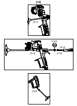
Page 121: ... 10 10 1 10 2 10 4 10 5 10 3 10 6 ...
Page 122: ... 11 a c b 11 1 11 2 11 1 11 2 11 3 11 4 ...
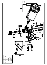
Page 123: ... 13 14 222489 ...
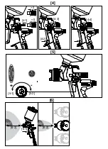
Page 126: ... 3 3 4 3 2 3 3 3 1 ...
Page 127: ... 4 5 6 4 3 4 4 6 1 4 1 5 1 5 2 0 0 90 90 6 2 6 2 4 2 ...
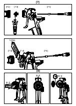
Page 128: ... 7 8 7 2 7 3 7 1 7 5 7 4 7 6 14 Nm 8 1 8 2 8 3 ...
Page 129: ... 9 9 1 9 3 9 2 3 1 2 ...
Page 130: ......

