background image

DS 1.002

2 - 4

02/99

SPECIFICATION

Sensor Control Range:

10 to 35

°

C.

Sensing Element:

Negative temperature coefficient thermistor.

Sensor Characteristics:

Non-linear. See page 3 for table of resistance values.

Sensor Wiring:

2-wire low Voltage dc, non-polarised to controller.

Switch Rating:

2.5A 250Vac. Motor full load current.12A motor starting, 250Vac

Note: Manual switches suitable for choke controlled or capacitor controlled fan motors only.

Slide switch.

Terminals:

Screw-type to accept one 2.5mm

2

wires.

Housing:

Tough fire resistant plastic case and backplate. Protection class IP20.

Ambient Temperature Limits: -10 to 55

°

C.

Associated Controller:

CZU temperature controller. Refer to DS2.201 for details.

IAC controller. Refer to DS2.951 or DS2.801 for details. A look up table module should be used to offset the
control module RPW input by -10

°

C if terminals A and B are used. If terminals A and C are used, set the control

module set value to 10

°

C.

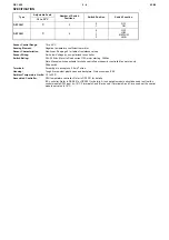
Type

Adjustable Scale

Number of Switch

Positions

Switch Position

Switch Function

10 to 35°C

DRT 3801

2

0
1

OFF

ON

DRT 3851

4

0
1
2
3

OFF

LOW

MEDIUM

HIGH

Summary of Contents for DRT Series

Page 1: ...s which are air conditioned by means of fan coil units The room occupant is provided with local adjustment of room temperature and also fan speed ON OFF or OFF 1 2 and 3 for optimum comfort settings The instrument can alternatively be applied as a remote temperature setting unit in conjunction with a DDU temperature sensor located in the fan coil unit return air space for example Alternative model...

Page 2: ...witch Terminals Screw type to accept one 2 5mm2 wires Housing Tough fire resistant plastic case and backplate Protection class IP20 Ambient Temperature Limits 10 to 55 C Associated Controller CZU temperature controller Refer to DS2 201 for details IAC controller Refer to DS2 951 or DS2 801 for details A look up table module should be used to offset the control module RPW input by 10 C if terminals...

Page 3: ...ace relays or contactors for fan circuits as required 6 Slide the mains cover over the mains terminals and tighten the fixing screw 7 CZU Controllers Only i Connect sensor wires to non polarised terminals A C of sensor when used as temperature sensor See Fig 3 Connect to terminals A B when used as remote setting unit See Fig 3 IAC Controllers Only i When connecting terminals A and C A is the commo...

Page 4: ...iring precautions See DS 2 201 2 801 or 2 951 Do not short circuit sensor terminals for test purposes Observe maximum ambient temperature Interference with those parts under sealed covers renders the guarantee void Design and performance of Satchwell equipment are subject to continual improvement and therefore liable to alteration without notice Information is given for guidance only and Satchwell...

Reviews: