background image


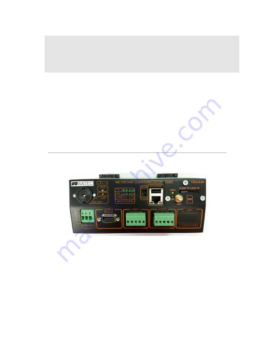
ETC II Network Communicator 


Installation and Operation Manual 


BG0594 Rev. A2 

Summary of Contents for ETC II

Page 1: ...ETC II Network Communicator Installation and Operation Manual BG0594 Rev A2 ...

Page 2: ...r and other power sources are turned OFF before performing any work on the instrument Failure to do so may result in serious or even fatal injury and or equipment damage Before connecting the instrument to the power source check the labels on the back of the instrument to ensure that your instrument is equipped with the appropriate power supply voltage input voltages and currents Under no circumst...

Page 3: ...ctions 14 Routing Messages over Slave Networks 15 Shared Device Access 16 ETC II Network Applications 16 ETC II Clock 19 Chapter 4 Connecting to the ETC II 20 Using HyperTerminal 20 Running HyperTerminal 20 Opening a Terminal Session 21 Closing a Terminal Session 22 Using Telnet 22 Running Telnet from HyperTerminal 22 Running the Telnet Client 23 Opening a Telnet Session 24 Closing a Telnet Sessio...

Page 4: ...nicator Configuring Dial Up Connections 38 Configuring Gateway Options 40 Configuring Device Routing Table 42 Configuring eXpertPower Client 43 Configuring Data Server 44 Chapter 6 Upgrading Device Firmware 50 Chapter 7 Device Maintenance 51 Appendix Technical Specifications 53 ...

Page 5: ...and wireless devices The application can also write data to slave devices via the ETC II exchanges instead of waiting until a remote device is accessible The Data server may be programmed to monitor the slave device s status registers for specific events and to record them to a log file and send alerts to a remote server Features Ethernet 10 100Base T port communicating to the IP network Service U...

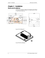
Page 6: ...ter 2 Installation Mechanical Installation The ETC II can be located on a table top or be mounted on a 35 mm DIN rail or on a panel See Figures 2 2 through 2 4 for mounting instructions Figure 2 1 shows the device dimensions Figure 2 1 ETC II Dimensions Figure 2 2 Table Top Placement ...

Page 7: ... Chapter 2 Installation Mechanical Installation ETC II Network Communicator 7 Figure 2 3 Din Rail Mounting Figure 2 4 Panel Mounting ...

Page 8: ...ormally used for servicing and setting up the ETC II It can also be used as a slave port for serial to serial communications via the ETC II gateway The COM4 and optional COM5 gateway ports are used for connecting the ETC II to the RS 422 RS 485 slave networks with up to 32 devices on each network For device routing rules see Routing Messages over Slave Networks in Chapter 3 The COM4 port can also ...

Page 9: ...lation ETC II Network Communicator 9 Figure 2 6 Serial Network Connection COM3 RS 232 Connection Figure 2 7 Simple RS 232 3 Wire Connection 9 pin Female Connector Figure 2 8 Simple RS 232 3 Wire Connection 25 pin Connector ETC II ETC II ETC II ...

Page 10: ...ectrical Installation 10 ETC II Network Communicator COM4 COM5 RS 422 RS 485 Connection Figure 2 9 Multidrop RS 422 Connection Figure 2 10 Multidrop RS 485 Connection Figure 2 11 Multidrop RS 485 Connection ETC II ETC II ETC II ...

Page 11: ...hernet hub jack and the other end into the RJ45 jack at the front of the ETC II marked ETHERNET Figure 2 12 Network Connections See Internet Connections in Chapter 3 and configuring the Network in Chapter 5 for instructions on how to program your device for networking via Ethernet CELLULAR Port optional A 2G 3G Cellular modem port provides a direct connection of the ETC II to a public area cellula...

Page 12: ...e position of the PROG RUN switch the COM3 service port is available for communications via a Terminal program or for master communications The CPU LED flashing briefly 2 times with a one second pause indicates that the device is in service mode and is not operational The CPU LED flashing briefly 3 times with a one second pause indicates that a critical error has occurred and the device is not ope...

Page 13: ...ateway port The COM5 port is factory set to master mode See Configuring Serial Ports in Chapter 5 for information on programming serial ports The communication protocol to be used for serial networking via the ETC II is defined by the Network TCP service port setting See Configuring the Network in Chapter 5 for information on programming the ETC II TCP service port Wireless RF Network Connections ...

Page 14: ...dditional server either on the DNP3 TCP port 20000 or on the SATEC ASCII TCP port 5002 allowing simultaneous connections on both ports The TCP server can be accessed via a local Ethernet network or via a Dial up PPP Internet connection using an embedded 56K modem The ETC II Dial up port is programmable either for dial in connections from a remote TCP client via Windows Dial Up Networking services ...

Page 15: ...is redirected to the default Ethernet gateway Serial Master Connections The ETC II can also be used as a serial to serial or a serial to wireless gateway This provides connections to slave networks from serial applications using the COM3 RS 232 or the COM4 RS 422 485 slave port To use the COM3 port as a slave port 1 Configure the COM3 port communication parameters for your master application See C...

Page 16: ...hat or another file in the same device could destroy file buffers such that both clients may receive corrupted data To avoid possible collisions the ETC II offers you two options 1 First you can entirely disable shared device access so that the ETC II rejects any additional requests addressed to a device that is being accessed by another client In this event the ETC II returns an exception respons...

Page 17: ...nges Refer to the ETC II Modbus Guide for information on accessing and retrieving data from the Data server exchanges Real Time Data Exchanges Real time data exchanges are used for periodic retrieval of data from the connected devices The ETC II provides up to 250 real time data exchanges of 1 to 114 registers long They are directly accessible from remote master applications When the Data server i...

Page 18: ... in the device either as coils or as holding registers you should specify a register type for each event exchange Write Data Exchanges The Data server can provide remote writing data to serviced devices upon user request Up to 250 write exchanges are supported with a size of 1 to 12 registers The following table shows the write exchange layout Write Exchange Block Description Range Exchange number...

Page 19: ...ach second normally with accuracy better than 1 millisecond if the time is synchronized with the GPS satellite time If the GPS clock loses the satellite signal the clock continues to generate the IRIG B time code referenced to the last available satellite time but the time quality may deteriorate Such signal losses can last from a few minutes to several hours During such outages the time code gene...

Page 20: ...nal is also used for servicing the ETC II and upgrading the device firmware Running HyperTerminal 1 Connect your PC to the ETC II COM3 RS 232 port using the standard RS 232 DTE DTE null modem cable that came with your ETC II 2 Run HyperTerminal from the Windows Start Programs Accessories Communications menu Type a name for your new connection and click OK In the Connect Using box select the PC COM...

Page 21: ...ist of the available commands as follows ETC II Ethernet Converter Ver 21 X X SATEC TCP Server Modbus TCP Server DNP3 0 TCP Server Copyright C 2002 SATEC Ltd ETC Terminal commands h Displays this text ver About ETC version password Password setting ip TCP IP settings port TCP service port number b Change the terminal baud rate COM Port Baud Data Serial port settings Port 3 4 5 Baud 1200 57600 Data...

Page 22: ...er the communications security is enabled or disabled After receiving the Terminal prompt you may enter your commands Closing a Terminal Session To close your terminal session put the PROGRAM RUN key on the ETC II in the RUN position Using Telnet Unlike HyperTerminal Telnet allows you to access the device through a local network or from any location on the Internet where your device is visible Jus...

Page 23: ...ess in the Host address box and set the port number to 5023 Click OK Running the Telnet Client 1 From the Start menu select Run type telnet and click OK The following text appears in a window Microsoft R Windows 2000 TM Version 5 00 Build 2195 Welcome to Microsoft Telnet Client Telnet Client Build 5 00 99206 1 Escape Character is CTRL Microsoft Telnet ...

Page 24: ... time hh mm ss Time date dd mm yy Date log Prints network log stat Prints network statistics stat ip Prints current network IP addresses stat xp Prints XP client status service Service Menu datasrv Data server configuration run dump Starts dumping the log to console run server Starts the TCP server stop dump Stops dumping the log to console stop server Shuts the TCP server down reset Resets the de...

Page 25: ...t application or for connecting to the ETC II Telnet server from the Windows Telnet client To use Windows Dial Up Networking for dial in connections create a new Dial Up connection for your ETC II 1 From the Start menu select Settings Network and Dial Up Connections Make New Connection 2 Select Dial up to the Internet and click Next 3 Select I want to set my Internet connection manually and click ...

Page 26: ...r 4 Connecting to the ETC II Dial Up Networking 26 ETC II Network Communicator 5 Select a modem you use to connect to the Internet and click Next 6 Type the telephone number of the ETC II modem and click Next ...

Page 27: ...Networking ETC II Network Communicator 27 7 Leave the user name and password boxes blank and click Next In dial in mode the ETC II does not require the name and password to login 8 Type the connection name and click Next 9 Check No and click Next ...

Page 28: ...can be used for configuring the ETC II via the Internet See the PAS Getting Started Guide supplied on the installation CD for information on how to install PAS on your PC Configuration Database To communicate with the ETC II from PAS create a site database for your device All communication and configuration data for your device will be stored in this database During configuration store all setups ...

Page 29: ...mmunicating through the Ethernet To communicate through the Ethernet port 1 On the Instrument Setup tab select Internet Site 2 Click on the Connection tab 3 Click on the IP address and type in the IP address that you defined in Network Setup in your ETC II The factory set default IP address is 192 168 0 203 4 In the Protocol box select the communications protocol for the ETC II TCP port The host p...

Page 30: ...onnection tab 3 Click on the IP address and type in the IP address your meter got from the CELLULAR provider when registering on the CELLULAR network You can find the meter CELLULAR IP address on the GPRS page in the Device Info display see Device Info Display in Chapter 3 or via the Dial Up Networking setup dialog in PAS see Modem GPRS IP Address in Setting Up Dial Up GPRS Network in Chapter 5 4 ...

Page 31: ... ETC II PAS allows you to prepare setup data for the ETC II offline without the need to have it connected to your PC Select the ETC II site from the list box on the PAS toolbar and then select the desired setup group from the Meter Setup menu Click on the tab with the setup you want to create or modify and then fill in the boxes with the desired configuration data Click the Save as button to store...

Page 32: ...e PAS toolbar select the device site from the list box on the toolbar and then select Download Setups from the Meter Setup menu Uploading Setup from the ETC II To upload the setup from the ETC II to the site database check the On line button on the PAS toolbar select the device site from the list box on the toolbar and then select Upload Setups from the Meter Setup menu Authorization If communicat...

Page 33: ...d when prompted and press Enter To leave the password unchanged just press Enter New Password 0 99999999 Repeat Password 0 99999999 Type y to enable or n to disable password checking and then press Enter To leave the current setting unchanged just press Enter Comm Network Protection Enabled y n N New Y Using PAS To change the password check the On line button on the PAS toolbar select Administrati...

Page 34: ...n minutes from UTC Universal Coordinated or Greenwich Mean Time It is used to produce a local time from the GPS IRIG B time code Daylight savings time Disabled Enabled Disabled When DST is disabled the RTC operates in standard time only When enabled the device automatically updates the time at 2 00 AM at the pre defined DST switch dates DST start month DST start week DST start weekday Month week w...

Page 35: ... clock for daylight savings time Configuring Serial Ports Using HyperTerminal or Telnet To view the present serial port settings type com and press Enter com COM3 19200 8N COM4 9600 8N COM5 9600 8N To change the serial port settings type com followed by the port number baud rate and data format separated by a space and press Enter as in the following example com3 19200 8N COM3 19200 8N COM4 9600 8...

Page 36: ... Ethernet Address Statistics ENET Name D Link DE 220 Ethernet driver IP address 192 168 0 213 Subnet mask 255 255 255 0 Gateway 192 168 0 1 PPP Address Statistics PNET Name Modem Driver IP address 192 168 10 203 Subnet mask 255 255 255 0 Gateway 192 168 10 204 To change the network settings type ip and press Enter If you wish to change a parameter type your new setting after the prompt and press E...

Page 37: ... more information on using dial out networking 2 When you change a network parameter the ETC II restarts the network to accept your new settings If you configure your device through telnet your current connection will be lost and you will be required to open a new session To view or change the ETC II TCP server port setting type port and press Enter port TCP service port 502 New The TCP service po...

Page 38: ...d just press Enter Refer to the table below for the available connection options and their description modem Number of dial attempts 0 New Connection timeout sec 180 New Delay between redials 1 New Idle connection timeout sec 60 New Rings before answer 8 New Modem init AT command ATZ0 F New 1 Phone number to dial New 1 Login name New 1 Login password New Network IP address 192 168 10 203 New Netwo...

Page 39: ...Setup tab The following table lists available connection options Parameter Options Default Description Connection Options IP Address 192 168 10 203 The IP address on the dial in modem PPP network Not used in a GPRS network Network Subnet Mask 255 255 0 0 The PPP GPRS network subnet mask Network Default Gateway 192 168 10 204 The PPP network default gateway Not used in a GPRS network Redial Attempt...

Page 40: ...ed GPRS Access Point Name APN internet The mobile network APN name consult with your network operator Note Do not change the default modem connection options Consult with your GPRS network operator if the network subnet mask needs to be extended Configuring Gateway Options Using HyperTerminal or Telnet To view or change the ETC II gateway settings type mbus and press Enter To change a parameter ty...

Page 41: ...The ETC II network ID Device Address Range Start 1 247 1 The start slave device address on the gateway Device Address Range End 1 247 215 The end slave device address on the gateway Routing Table Disabled Enabled Disabled Enables using the device routing table Shared Device Access Disabled Enabled Enabled Enables multiple accesses to slave devices from a number of clients ...

Page 42: ... Access in Chapter 3 for information on shared device accesses The following table lists available routing options Label Options Default Description Gateway Port Ethernet COM4 COM5 COM4 The ETC II port to which the device addressed messages will be routed Device IP Address 192 168 0 203 The Ethernet device IP address Shared Device Access Rules None no access limitations 1 PM296 family PM296 PM171 ...

Page 43: ...w y n Connection period min 10 New Time to next session 0 See the table below for available options Refer to your eXpertPower service provider for the correct eXpertPower settings See eXpertPowerTM Client in Chapter 3 for more information on the eXpertPower TM service NOTES 1 If you do not use the eXpertPower TM service do not enable the eXpertPower client in your ETC II 2 Do not change the connec...

Page 44: ...v You will be prompted for the password The factory set password is 0 unless you have changed it in your ETC II Enter password Data Server Configuration Commands h Display this text p Server parameters s N Set address range i N Display address range settings q Quit menu N address range number Data server Data Server Options To view the Data server options type i and press Enter Data server i Data ...

Page 45: ...he ETC II to the same device address Device ID 1 New Start device register address 256 New Number of registers 1 New 3 Enable real time polling for the exchange if you want to start exchange operations Polling enabled New y n 4 Enable updating the real time clock in the device if you wish to periodically synchronize its clock with the ETC II clock RTC update disabled New y n 5 Specify the start de...

Page 46: ...e Data server options Parameter Options Default Description Polling Interval 1 1000 min 1 min Specifies the interval for periodic polling connected devices Logging Interval polls 0 1000 0 logging disabled 1 A non zero interval enables recording the acquired data to the log file at predefined intervals Data Server Operations Disabled Enabled Disabled Enables Data server operations Continuous Pollin...

Page 47: ...r synchronizes the device clock with the ETC II clock To configure a real time data exchange 1 Define the device address for a data exchange Note that the real time status event and write data exchanges with the same exchange number are internally linked in the ETC II to the same device address 2 Specify the start register address of the area in the device Modbus map you wish to be polled via the ...

Page 48: ...status register Auto Reset Disabled Enabled Disabled If enabled the Data server clears the device register after it has been read To configure a status event exchange 1 Define the device address for a status event exchange Note that the real time status event and write data exchanges with the same exchange number are internally linked in the ETC II to the same device address 2 Specify the device s...

Page 49: ...s the start device register for a write Block Size 1 12 0 Defines the number of contiguous registers in the write exchange Write Enabled Disabled Enabled Disabled Enables writing data to the device upon a trigger To configure a write data exchange 1 Define the device address for a write data exchange Note that the real time status event and write data exchanges with the same exchange number are in...

Page 50: ... recommended to set the serial port baud rate to 115 200 bps See Configuring Communications on how to remotely change the protocol and baud rate in your meter To download a firmware file to your meter 1 Check the On line button on the PAS toolbar select Flash Downloader from the Monitor menu and then confirm changes 2 Point to the firmware upgrade file click Open and then confirm upgrading the met...

Page 51: ...is chapter describes the battery replacement procedure See Figures 7 1 to 7 4 for replacement instructions Observe the battery polarity The battery polarity appears on the inner part of the battery cover Figure 7 1 Battery Housing Location of the Panel Figure 7 2 Battery Housing Cover Removal ...

Page 52: ... Chapter 7 Device Maintenance 52 ETC II Network Communicator Figure 7 3 Battery Removal Figure 7 4 Insertion of New Battery ...

Page 53: ...on 3200 VRMS 12 VDC Option Rated input 9 6 19 VDC 24 VDC Option Rated input 19 37 VDC 48 VDC Option Rated input 37 72 VDC Burden 10W Isolation except 12VDC 1350 VRMS Wire size up to 12 AWG up to 2 5 mm 2 Communication Ports COM1 Ethernet Port Transformer isolated 10 100BaseT Ethernet port Connector type RJ45 modular Supported protocols Modbus TCP port 502 SATEC ASCII TCP port 5001 and DNP3 TCP por...

Page 54: ...ator Wire size up to 12 AWG up to 2 5 mm 2 Terminals pitch 5 mm Baud rate up to 115 2 kbps Supported protocols Modbus RTU SATEC ASCII and DNP3 Real time Clock Accuracy typical error 15 seconds per month 25 C Log Memory Onboard memory with battery backup 4 Mbytes ...

Reviews: