Chapter 3 Operating the ETC II
Using the ETC II
ETC II Network Communicator
13
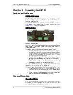
To put the ETC II into operational mode, set the PROG-RUN switch in the
RUN position.
Program Mode
In program mode, the COM3 port operates as a service port that allows the
user to review or change settings in the device via a Terminal program (see
Using HyperTerminal
in Chapter 4 for more information). The device still
services the Internet to serial gateway connections, but serial-to-serial
master connections through the COM3 port are not available.
To put the device into program mode, set the PROG-RUN switch in the
PROG position.
Service Mode
Service mode is used for local device servicing and upgrading firmware
through a Terminal program. In service mode, the Internet-to-serial gateway
is not operational.
The device enters service mode either from program mode upon an explicit
user command sent via a Terminal program, or when the device is powered
with the PROG-RUN switch set in the PROG position. See
Upgrading
Device Firmware
in Chapter 6 for instructions.
Using the ETC II
Slave Network Connections
Serial Network Connections
The ETC II is connected to serial RS-422/485 slave networks via the COM4
and COM5 gateway ports.
The COM4 should be set to master mode to operate as a gateway port. The
COM5 port is factory-set to master mode. See
Configuring Serial Ports
in
Chapter 5 for information on programming serial ports.
The communication protocol to be used for serial networking via the ETC II
is defined by the Network TCP service port setting. See
Configuring the
Network
in Chapter 5 for information on programming the ETC II TCP
service port.
Wireless RF Network Connections
The COM5 port can be configured to support a wireless RF ZigBee slave
network built on a Helicomm IP-Link platform.
The IP-Link network is an expandable, low-rate wireless ZigBee platform,
which allows various configurations, including mesh network topology to be
programmed by the user to best match the installation conditions and
applications networking needs. A network may contain up to 30 remote
nodes with full mesh support and can operate at one of the seven
frequencies from 907MHz to 922MHz to avoid interference with other
ZigBee networks.
Slave ZigBee devices are provided with the embedded IP-Link 1000
modules. The ETC II is connected to a ZigBee network via an external IP-
Link 2000 modem that operates as a master node.
A wireless network is used as a transparent media for delivering Modbus
RTU messages. To identify devices on the network, each slave node is
assigned a network ID that is identical to the device Modbus address. See
Configuring Wireless RF Connections
in Chapter 5 for information on
configuring the IP-Link module parameters in the ETC II.


