Chapter 5 Setting Up the ETC II
Configuring Data Server
48
ETC II Network Communicator
See
Data Server
in Chapter 3 for more information on using status event
exchanges. Refer to the ETC II Modbus Guide for information on how to
access the event log data via communications.
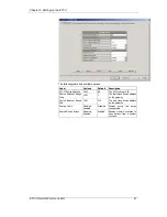
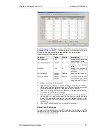
The following table lists available options.
Parameter
Options
Default
Description
Device address
1-247
1
Defines the device to which
the exchange is linked
Register Address
0-65535
0
Defines the device status
event register address for
polling
Event Mask
0-0xFFFF
0
Defines the bit mask for
bits which status must be
checked for events
Polling Enabled
Disabled,
Enabled
Disabled
Enables polling the status
register
Auto Reset
Disabled,
Enabled
Disabled
If enabled, the Data server
clears the device register
after it has been read
To configure a status event exchange:
1.
Define the device address for a status event exchange. Note that the
real-time, status event and write data exchanges with the same
exchange number are internally linked in the ETC II to the same device
address.
2.
Specify the device status register address you wish to be polled via the
exchange.
3.
Specify the event mask for bits you wish to be checked for events.
4.
Check the “Polling Enabled” box to activate the exchange.
5.
Check the “Auto Reset” box if you want the status register to be cleared
after polling.
Write Data Exchanges
To enter the Setup dialog, select the ETC II site from the list box on the PAS
toolbar, select ETC II Setup from the Meter Setup menu, and then click on
the Write Data Exchanges tab.


