background image


    SATELLINE-M3-TR3, 

TR4 and -R4 

Integration Guide, Version 3.0 


23


6


CONFIGURATION


The configuration of settings can be changed easily - the next chapters describe the details: 
 

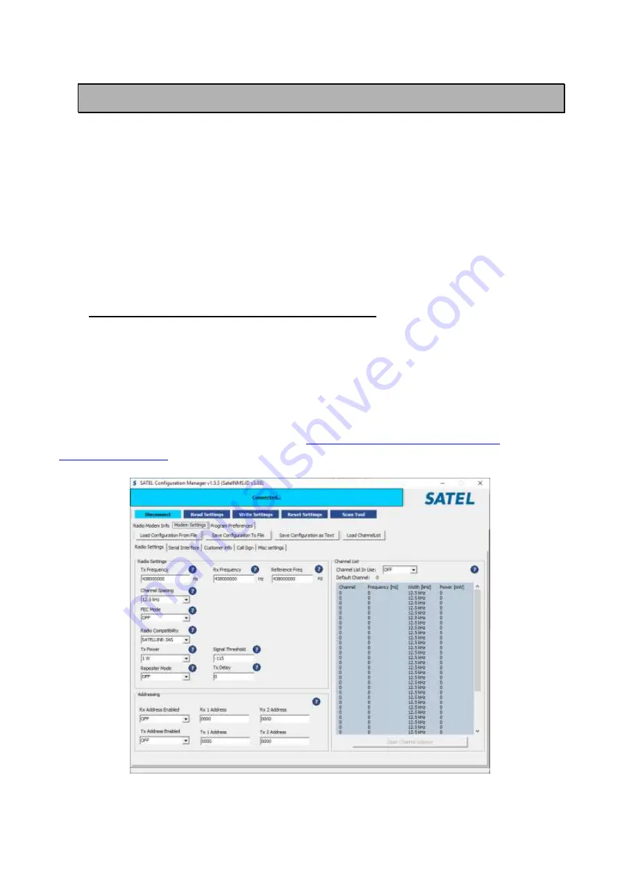
SATEL Configuration Manager PC software 

This clear to use software suits in most cases. Additional to other tools, it includes the channel 
list editor for creating the channel lists. 
 

SL commands 

A terminal device can command or configure the radio modem by using special commands. SL 
commands are applied especially in cases where radio modems are to be integrated seamlessly 

inside a system behind the integrator’s own user interface.


6.1


SATEL Configuration Manager software 

 
SATEL Configuration Manager is a PC software for the configuration of SATELLINE-M3-R/TR, 
SATEL-R/TR 

module based radio models, covering most of the SATEL radio products.  

 
Minimum requirements: PC (Windows 95, 98, 2000, XP, Vista and Win7) equipped with a COM 
port (USB-RS adapters available) and the radio modem, powered up, to be configured. 
 
The software is available from the dealers or at 

https://www.satel.com/support-and-

services/downloads/

. 


Summary of Contents for ATELLINE-M3-R4

Page 1: ...SATELLINE M3 TR3 TR4 AND R4 MODULE INTEGRATION GUIDE Version 3 0 ...

Page 2: ... The manufacturer does not grant any kind of warranty including guarantees on suitability and applicability to a certain application Under no circumstances is the manufacturer or the developer of a program responsible for any possible damages caused by the use of a program The names of the programs as well as all copyrights relating to the programs are the sole property of SATEL Any transfer licen...

Page 3: ...product labeling requirements SATELLINE M3 TR3 and TR4 is intended to be integrated into a host device Therefore the SATELLINE M3 TR3 and TR4 product related FCC ID and IC ID must be visible in the host device chassis FCC ID MRBSATEL TA23 IC 2422A SATELTA23 Class B digital device statement Note This equipment has been tested and found to comply with the limits for a Class B digital device pursuant...

Page 4: ... interference by one or more of the following measures Reorient or relocate the receiving antenna Increase the separation between the equipment and receiver Connect the equipment into an outlet on a circuit different from that to which the receiver is connected Consult the dealer or an experienced radio TV technician for help ...

Page 5: ...with the essential requirements radio performance electromagnetic compatibility and electrical safety and other relevant provisions of Directives 2014 53 EU and 2011 65 EU and Council recommendation 1999 519 EC Therefore the equipment is labeled with the following CE marking The operating frequency range of the device is not harmonized throughout the market area and the local spectrum authority sh...

Page 6: ...SATELLINE M3 TR3 TR4 and R4 Integration Guide Version 3 0 5 ...

Page 7: ...d at frequencies allocated by local authorities and without exceeding the given maximum allowed output power ratings SATEL and its distributors are not responsible if any products manufactured by it are used in unlawful ways The devices mentioned in this manual are to be used only according to the instructions described in this manual Faultless and safe operation of the devices can be guaranteed o...

Page 8: ...on of the products 10 1 3 DTE connector 11 1 4 Pin order of the DTE connector 12 2 MECHANICAL CONSIDERATIONS 14 2 1 Fixing device to host 14 2 2 Host board instructions for mounting pegs 14 2 3 Heat transfer 15 3 TECHNICAL SPECIFICATIONS 16 3 1 Absolute maximum ratings 18 3 2 DC electrical specifications 18 4 DEFAULT DELIVERY VALUES 19 5 TIME PARAMETERS FOR STARTUP AND SHUTDOWN SEQUENCES 20 5 1 St...

Page 9: ...5 7 OPERATING MODES 26 7 1 Safe mode 26 7 2 Power up power down scenarios 26 7 3 Sleep Mode 27 7 4 Power Save Mode 27 7 5 Restart 28 8 SERIAL PORTS 29 8 1 Pause length 29 8 2 Data buffering 30 9 RF INTERFACE 31 9 1 Transmitter 31 9 2 Receiver 32 9 3 Encryption 32 9 4 Radio state 33 9 5 Priority RX TX 34 9 6 Forward Error Correction FEC 34 9 7 Error checking 34 9 8 TX Delay 35 9 9 Separate TX RX fr...

Page 10: ... 40 9 12 3 Support for Local Remote addresses 40 9 12 4 Transmission delays 41 10 CONSIDERATIONS 43 10 1 EMI Interferers 43 10 2 Electrostatic discharge 44 10 3 Using the device in unmanned high reliability applications 44 11 PROPOSALS FOR MORE RELIABLE RADIO LINK 45 12 APPENDIX 46 12 1 SL COMMANDS 46 12 1 1 Encryption commands 53 13 APPENDIX A 55 13 1 Transmission delays 55 14 VERSION HISTORY 58 ...

Page 11: ...handshaking signal used in asynchronous communication DTE Data Terminal Equipment typically computer terminal ESD Electrostatic discharge RD Receive Data TD Transmit Data RTS Ready To Send handshaking signal used in asynchronous communication RAM Random Access Memory LDO Low dropout regulator UHF Ultra High Frequency RF Radio Frequency FPGA Field programmable gate array CPU Central processing unit...

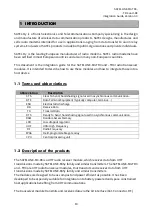
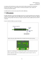
Page 12: ...s through connector This connector allows the pin to enter the connector from the bottom side and protrude thru the module PCB to the top side allowing flexible mounting heights with various pin lengths Separate models available with top side DTE connector Entry from bottom of device see picture below Figure 1 Side view of the module with 1 27mm pitch connector and screw fixing Figure 2 Pin number...

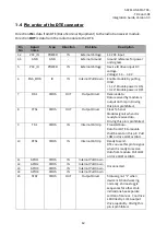
Page 13: ...by module is output on this pin Driving this pin is prohibited 8 CTS1 CMOS OUT Output Driver Clear To Send Module signals when it is ready to receive data Driving this pin is prohibited 9 TD1 CMOS IN Internal Pull Up Transmit Data Data from DTE to module shall be sent on this pin Pull LOW or drive LOW or HIGH 10 RTS1 CMOS IN Internal Pull Up Ready to send DTE can use this pin to signal when it is ...

Page 14: ...17 SERVICE IN Internal Pull Up Input for service access Internally pulled high Pull LOW drive LOW to set UART1 RD1 TD1 into known state See separate section of manual 18 GPIO6 CMOS IN Internal Pull Down Unconnected 19 GPIO7 CMOS IN Internal Pull Down Unconnected 20 GPIO8 CMOS IN Internal Pull Down Unconnected ...

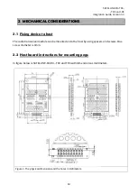
Page 15: ... to host The radio transceiver module can be mounted on to the host by using spacers and screws Max screw diameter is 3mm 2 2 Host board instructions for mounting pegs In figure below is SATELLINE M3 R4 TR3 and TR4 with dimensions as millimeters Figure 3 The physical dimensions and the holes in millimeters ...

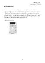
Page 16: ... space where large metal area is exposed This metal plated area between the mounting holes is the area that can be used to transfer heat away from the board There are few alternatives to transfer heat The simple and less effective way is to through the host carrier board by using a heat conductive element between the module Second method is to conduct heat directly to some mechanical structure whi...

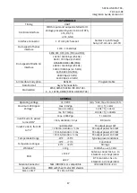
Page 17: ...aximum Receiver Input Power without Transmission Errors 10 dBm FEC ON Sensitivity 1 2 112 dBm 25 kHz 116 dBm 12 5 kHz FEC ON Blocking 1 2 86 dB 25 kHz 88 dB 12 5 kHz FEC ON Intermodulation Attenuation 1 2 61 dB 25 kHz 61 12 5 kHz FEC ON CO Channel Rejection 1 2 11 dB 25 kHz 10 dB 12 5 kHz FEC ON Adjacent Channel Selectivity 1 2 56 dB 25 kHz 51 dB 12 5 kHz FEC ON Spurious Rejection 67 dB FEC ON Typ...

Page 18: ...3 4 8 16FSK GMSK SATELLINE M3 TR4 GENERAL Operating voltage 4 0 VDC min 5 4 0V max Nominal 5 Maximum DC Ripple Voltage 3 max 9 mVpp DC f 1 kHz max 64 mVpp 1 kHz f 10 kHz mx 517 mVpp 10 kHz f 100 kHz max 2 035 Vpp f 100 kHz Inrush Current power turned ON 4 12A duration 50 µs RX mode Inrush Current from RX to TX 4 not detected TX output power 1W 150 mA duration 1 ms TX output power 500 mW 70 mA dura...

Page 19: ... ENA_MOD 0 3 V 6 V Voltage at VCC_IO 0 5 V 3 75 V Voltage at digital inputs except ENA_MOD 0 5 V 3 75 V Voltage at digital outputs when no power is applied to unit 0 5 V 3 75 V Antenna port power n a 14 dBm Antenna port DC voltage 10V 10V Table Absolute maximum ratings of module All voltages are referenced to GND 3 2 DC electrical specifications Over recommended operating conditions Parameter Cond...

Page 20: ...ASxE SATEL 8FSK 1 FEC OFF SATEL 8FSK 2 FEC ON SATEL 16FSK 1 FEC ON Addressing RX Address OFF ON OFF TX Address OFF ON OFF Serial port Data speed 115200 bps 1200 115200 bps Data bits 8 8 Parity bits None None Even Odd Stop bits 1 1 Handshaking Handshaking lines apply to the DATA port CTS TX Buffer State Clear to send TX Buffer State RTS Ignored Ignored Flow Control Additional setup Error Correction...

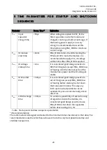
Page 21: ...ce to KEEP all IO signals except ENA_MOD low or floating until the internal parts of the module have power and the IO voltage is stable Tior IO drive fall time 300 µs It is considered good design practice to set all IO signals except ENA_MOD low or floating before starting to shut down the transceiver module This way any latch up brownout problems can be avoided IO pins are not internally driven a...

Page 22: ...tion Guide Version 3 0 21 5 1 Startup sequence The following diagram will describe the startup sequence Figure 7 Startup sequence 5 2 Shutdown sequence The following diagram will describe the shutdown sequence Figure 8 Shutdown sequence ...

Page 23: ...data Over the Air Pin is toggled in 1s interval Module has the connection to Configuration Manager program Pin is toggled in 500ms interval SL Command mode Pin is toggled in 250ms interval Module has detected a fault fault codes can be read via Configuration Manager program Table Modes of STAT pin 5 4 Service pin The SERVICE pin is used to set the UART1 into a known state Pulling this pin low will...

Page 24: ...ial commands SL commands are applied especially in cases where radio modems are to be integrated seamlessly inside a system behind the integrator s own user interface 6 1 SATEL Configuration Manager software SATEL Configuration Manager is a PC software for the configuration of SATELLINE M3 R TR SATEL R TR module based radio models covering most of the SATEL radio products Minimum requirements PC W...

Page 25: ...nsfer SL command is properly recognised also in the case when the command string is terminated by CR ASCII character no 13 Carriage Return 0x0d or CR LF LF ASCII char no 10 Line Feed 0x0a If multiple SL commands are sent to the module the next command can be given after receiving the response Ok or Error of the proceeding command In addition it is recommended to implement a timeout to the terminal...

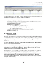
Page 26: ...ed by using the below described procedure Regardless of original SL command setting state changing the setting state with this procedure will effect to the reception process of the radio module SL command setting state can be changed only via SATEL Configuration Manager in maintenance access level Note1 To enable the SL Commands disables radio interface transmission and reception Send three charac...

Page 27: ... packets Decreases the power consumption of complete receiving cycle approx 30 7 1 Safe mode When a fault has been detected by the Firmware the module is set to Safe mode In this mode the module toggle s the Stat Pin in 250ms interval indicating an Error and reboots the device after 5s Transmitting Receiving is prohibited during malfunction When connecting to the device with SATEL Configuration Ma...

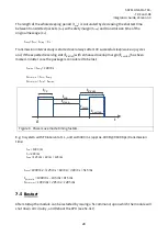
Page 28: ...example 0x00 2 Wait for OK response from the module The wake up time is approx 30 ms 3 Start communicating normally Module will remain powered ON until a new sleep command is issued 7 4 Power Save Mode The Power save mode performs an automatic self adjusting receiver wake up sleep cycle It is designed for applications which base on one way communication with relatively constant TX interval and in ...

Page 29: ... toverlap has been missed In latter case the package is considered to be lost toverlap tmarg 100 ms tRX slot min tmin tmarg tRX slot max tmin toverlap tTX tmin tRX slot t 0 tsleep toverlap tmarg Figure 4 Power save mode timing factors E g In system with TX interval of 1 s and with 300 ms approx 300B 9600 bps transmission time tmin 1000 ms tTX 300 ms tmarg 125 ms 60 ms 185 ms tsleep 1000 ms 125 ms ...

Page 30: ... the actual command character string User address recognition In order for the start character to be detected a pause must precede it in transmission Traditionally in asynchronous data communication pauses have been used to separate serial messages from each other However the use of non real time operating systems frequently used on PC type hardware often adds random pauses which may result in the...

Page 31: ...he speed of the radio interface the internal transmit buffer memory cannot overflow However when the serial interface speed exceeds the speed of the radio interface data will eventually fill transmit buffer memory In this instance it will take a moment after the terminal device has stopped transmission of data for the radio modem to empty the buffer and before the transmitter switches off The maxi...

Page 32: ...possible level such that it still ensures error free connection under variable conditions Excessively high output power levels used in short link spans can cause interferences and affect to the overall operation of the system Transmitter output power levels Output power mW Output power dBm 403 473 MHz 100 mW 20 dBm 200 mW 23 dBm 500 mW 27 dBm 1000 mW 30 dBm The antenna or a 50 Ohm attenuator shoul...

Page 33: ...imum sensitivity should be achieved and the desired signal is very weak In this case the sensitivity could increase by decreasing Signal threshold This type of situation is usually a sign of a poorly constructed radio network contact Bit errors and momentary loss of signals can be expected in this kind of a situation Some data might be successfully transferred The RSSI can be requested also locall...

Page 34: ...y via terminal connection o SL commands Automatically with password via Configuration Manager software generates automatically the Main and Aux keys It is recommended to set up a radio network with encryption enabled by using only one selected configuration way The password or the keys should be kept in a safe place as the keys can t be read from the device after configuration The equivalency of t...

Page 35: ...sfer over the radio by adding additional correction information to the radio messages Based on that information the receiving radio modem will be able to correct erroneous bits provided the ratio of erroneous and correct bits is reasonable However the use of FEC decreases the data throughput because the amount of transmitted data increases about 30 see Appendix A FEC should be used on long distanc...

Page 36: ...buffered Even when the priority setting is RX the radio modem is prevented to change over to the receiving mode during the period of the TX delay If TX delay is not needed its value should be set to 0 ms 9 9 Separate TX RX frequencies Modem can transmit TX frequency and receive RX frequency on separate frequencies The switch between the frequencies introduces an extra 40 ms delay in the data trans...

Page 37: ...radio modems in the network In large systems with several repeaters and formed repeater chains it is often practical to use routing instead of plain addresses In circumstances where it is necessary to extend the coverage area of a radio modem network modem can be used as repeater stations The maximum size of a repeated data packet is 1kB kilobyte The Repeater Function is switched on in the radio s...

Page 38: ...mode See list below TRIMTALK 450s compatible data transfer over the air This product provides the following radio compatibility options SATEL Original SATEL 3AS default 4FSK data transfer mode option 0 SATEL 8FSK 1 option 20 8 FSK FEC OFF TR R4 only SATEL 8FSK 2 option 21 8 FSK FEC ON TR R4 only SATEL 16FSK 1 option 22 16 FSK FEC ON TR R4 only PacCrest 4FSK Transparent mode FEC ON Scrambling ON Op...

Page 39: ...cific Crest modems receive messages from SATELLINE modems that have their TX1 address matching the Local Address Remote address 0 255 255 by default that is the broadcast address to be received by all SATELLINE modems receive the message from a Pacific Crest radio provided their RX1 address matches the Remote Address of a Pacific Crest transmitter or if the message has the broadcast address 255 SA...

Page 40: ...ermine the link rate Radio Link Modulation Mode Radio compatibility Radio Link Scrambling ON by default Radio Link Transmit Retries not implemented Radio Link TX ACK Timeout not implemented Radio Link Csma Monitoring Priority RX ON TX OFF Default RX Radio Link AutoBase AutoRover not implemented Radio Link Digisquelch Signal threshold Radio Link Forward Error Correction ON by default Note SATELLINE...

Page 41: ... SATEL FEC OFF temporarily and turns it back at the mode return Note 2 Unlike SATELLINE 3AS and Pacific Crest compatibility modes TRIMTALK 9 12 3 Support for Local Remote addresses If the modem has TX address ON then primary TX address is handled in the same way as Remote address in Pacific Crest PDL modems The default value is 0x00FF 255 in decimal format i e the broadcast address If the modem ha...

Page 42: ... bps PacCrest GMSK 4800 bps 9600 bps Trimtalk450s 4800 bps 9600 bps PacCrest FST 9600 bps 19200 bps The typical latency vs the size of a message is shown in the tables below for each radio compatibility mode The delays are measured from the end of transmitted data to the end of received data on the serial interface Pacific Crest 4FSK mode on 12 5 kHz channel Transfer delays Bps 1 byte 10 bytes 100...

Page 43: ...400 151 ms 168 ms 341 ms 1113 ms Trimtalk450s modes on 25 kHz channel Transfer delays Bps 1 byte 10 bytes 100 bytes 500 bytes 9600 82 ms 98 ms 267 ms 1017 ms 19200 80 ms 93 ms 215 ms 756 ms 38400 79 ms 89 ms 187 ms 625 ms Radio compatibility Option 5 Pacific Crest FST on 12 5 kHz channel Bps 1 byte 10 bytes 100 bytes 500 bytes 9600 47 ms 71 ms 261 ms 1145 ms 19200 45 ms 64 ms 207 ms 883 ms 38400 4...

Page 44: ...eration and speed etc While the module has an approx 10 dB S N requirement this constitutes that any signal entering the radio antenna on receive frequency on a level of 125 dBm 115dBm 10dB causes desensitization of the radio on that particular channel Example An interferer has a level of 100dBm on the frequency 421 MHz The radio will show an approximate sensitivity of 90dB 100dBm S N requirement ...

Page 45: ...14D Human Body Model Test conditions 1 5 kΩ 100 pF Module surface 1kV n a Table ESD ratings Measured Acc to EN 61000 4 2 specification 10 3 Using the device in unmanned high reliability applications The module features software and hardware watchdogs which are incorporated inside the CPU While we believe that this is a reliable method of keeping the module in operational condition there are parts ...

Page 46: ...s measured to find out whether the radio environment is clean enough by using a spectrum analyzer or radio module s RSSI Received Signal Strength Indication value Co operation with the local authority to find out the optimum free radio channel If the channel is disturbed an external band pass filter can be used for improving the filtering If at the adjacent channel is TDMA Time Domain Multiple Acc...

Page 47: ...ode 0 TX address OFF 1 TX address ON Addressing SL Q x Set TX address ON OFF Values of x are 0 TX address OFF 1 TX address ON OK or ERROR Addressing SL R Get primary receive address RX1 yyyy Addressing SL R xxxx Set receive addresses RX1 RX2 to value xxxx 0000 ffff OK or ERROR Addressing SL S Get secondary transmit address TX2 and secondary receive address RX2 xxxx yyyy Addressing SL S xxxx yyyy S...

Page 48: ... n Set modem to channel number n in channel list OK or ERROR ChannelList SL L nn Get channel info Index nn 0 number of channels 1 Channel number Frequency Channel width Tx Power For example CH 1 430 150000 MHz 25 0 kHz 100 mW 0D ChannelList SL L Iaa Nbbbb bb Fccc cccccc Wdd ddd Peeee e CR I Index field aa 0 39 Future reservation 0 255 N Channel number field bbbbbb 32767 32767 F Tx Rx Frequency fie...

Page 49: ...number_of_stop bits OK or ERROR DataPort SL L Get pause length Decimal number DataPort SL L n Set pause length OK or ERROR Memory SL Save current settings as permanent settings OK or ERROR Memory SL R Restore settings to their factory set values OK or ERROR ModemInfo SL H Get radio HW info HW nnnnn ModemInfo SL V Get modem type Depending on variant for example M3 TR3 ModemInfo SL 1 Get arbitrary d...

Page 50: ...nnn nnnnn MHz RadioFreq SL W Get lower limit of frequency band 2 nnn nnnnn MHz RadioFreq SL Y Get upper limit of frequency band 2 nnn nnnnn MHz RadioFreq SL F Get active frequency nnn nnnnn MHz RadioFreq SL F nnn nnnn n Set active frequency to nnn nnnnn MHz OK or ERROR RadioFreq SL FR Get Rx frequency nnn nnnnn MHz RadioFreq SL FR nnn nnn nn Set Rx frequency to nnn nnnnn MHz OK or ERROR RadioFreq ...

Page 51: ...cter where a CallSignState 0 OFF 1 ON b CallSignInterval 0 255 in minutes c CallSignId max 16 alphanumeric characters For example 1 5 MYMESSAGE followed by Carriage Return character RadioProperty SL C a b c Set Call Sign settings a CallSignState 0 OFF 1 ON b CallSignInterval 0 255 in minutes c CallSignId max 16 alphanumeric characters OK or ERROR RadioProperty SL D Get Tx delay ms For example 0 ms...

Page 52: ...SL F Get noise level of radio channel xxx dBm RadioProperty SL M Get repeater function O Repeater OFF character O R Repeater ON RadioProperty SL M x Set repeater function Values of x are O Repeater function OFF character O R Repeater function ON OK or ERROR RadioProperty SL P Get transmitter output power One of these values 100mW 200mW 500mW 1000 mW Rx only modems reply with 0 mW RadioProperty SL ...

Page 53: ... Option1 2 PacCrest GMSK Option2 3 Trimtalk450s P Option 3 RX fits PacCrest modems 4 Trimtalk450s T Option 4 RX fits Trimble modems 5 PacCrest FST Option5 6 SATELLINE 2ASxE 20 8FSK FEC OFF TR4 only 21 8FSK FEC ON TR4 only 22 16FSK FEC ON TR4 only 23 PacCrest 4FSK FEC Off Scrambler On 24 PacCrest GMSK FEC Off Scrambler On 26 PacCrest 4FSK FEC Off Scrambler Off 27 PacCrest GMSK FEC Off Scrambler Off...

Page 54: ...x or 1 Rx only Operation mode SL S x Activate sleep mode 1 turn the modem into a state where it will hold serial interface parts of the module on wakeup will take approx 30ms 5 Turns ON Power save mode 6 Turns OFF Power save mode OK or ERROR Operation mode SL Z 0 SL commands are OFF working then only in the command mode and CR LF feature OFF OK or ERROR Operation mode SL Z 1 SL commands are always...

Page 55: ...ide Version 3 0 54 SL K Get Key hash Response is to be used for the key match check SL A Get Key hash Response is the same for SL K and SL A SL A Main key Set Main key 32 characters 1 9 A F a f SL A AUX key Set AUX key 32 characters 1 9 A F a f ...

Page 56: ...AS mode FEC OFF on 12 5 kHz channel Transfer delays Bps 1 byte 10 bytes 100 bytes 500 bytes 1200 40 ms 40 ms 29 ms 22 ms 4800 34 ms 34 ms 31 ms 22 ms 9600 32 ms 32 ms 32 ms 27 ms 19200 32 ms 35 ms 64 ms 193 ms 38400 32 ms 36 ms 91 ms 352 ms SATELLINE 3AS mode FEC ON on 12 5 kHz channel Transfer delays Bps 1 byte 10 bytes 100 bytes 500 bytes 1200 52 ms 49 ms 48 ms 50 ms 4800 45 ms 45 ms 44 ms 44 ms...

Page 57: ...tected when there is a pause in data After that data is framed and transmitted over the radio Likewise the reception is done fully before outputting the message to the serial port Symbol rates of the compatibility modes The actual raw data rate is appr 2 3 of the symbol rate Compatibility mode Symbol rate on 12 5 kHz channel Symbol rate on 25 kHz channel PacCrest 4FSK 9600 bps 19200 bps PacCrest G...

Page 58: ...400 48 ms 51 ms 198 ms 878 ms Trimtalk450s modes on 12 5 kHz channel Transfer delays Bps 1 byte 10 bytes 100 bytes 500 bytes 9600 153 ms 177 ms 421 ms 1505 ms 19200 151 ms 172 ms 368 ms 1244 ms 38400 151 ms 168 ms 341 ms 1113 ms Trimtalk450s modes on 25 kHz channel Transfer delays Bps 1 byte 10 bytes 100 bytes 500 bytes 9600 82 ms 98 ms 267 ms 1017 ms 19200 80 ms 93 ms 215 ms 756 ms 38400 79 ms 89...

Page 59: ...ral modifications 1 1 01 11 2013 Added RF Exposure warning and host device labeling requirements 1 2 09 01 2014 Modified RF Exposure warning 1 3 14 05 2014 Measurement image updated 1 5 07 05 2015 Output power corrected DoC added 1 6 22 05 2015 Added TR4 information 1 7 29 10 2015 Chapter 6 2 table corrected 1 9 13 07 2016 Added DoC and SL commands 2 0 13 04 2017 Added Chapter 9 PROPOSALS FOR MORE...

Reviews: