SATEL CA-64E
3
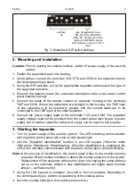
Fig. 3. Example of DIP switch settings.
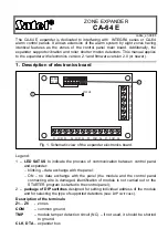
2. Mounting and installation
Caution: Prior to starting the module hookup, switch off power supply of the security
system.
1. Fasten the expander board in its housing.
2. Using cables, connect the terminals CLK, DTA and COM to the expander bus on
the control panel main board.
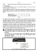
3. Using the DIP switches, set up the appropriate expander address and the type of
the supported detectors.
4. Connect the detector leads (for connection description refer to the alarm control
panel installer manual).
5. Connect the leads of the tamper contact on expander housing to the terminals
TMP and COM. Where two expanders are installed in the housing, the TMP input
of one expander is to be shorted to ground, and the contact leads are to be
connected to the TMP input of the other expander.
6. Connect the power supply leads to the ter12V and COM. The expander
supply voltage need not be provided from the control panel main board. A power
supply unit or another expander with power supply can be used for this purpose.
3. Starting the expander
1. Turn on power supply of the security system. The LED indicating communication
with the alarm control panel will come on with steady light.
2. Call the "Expander identification" function in the LCD keypad (
Æ
Service mode
Æ
Structure
Æ
Hardware
Æ
Identification). When the identification is completed, the
LED which indicates communication with the alarm control panel will start blinking.
Note: In the process of identification, the control panel writes to the module memory
a special (16-bit) number intended to detect the module presence in the system.
Replacement of the expander with another (even one having the same address
set up on the switches) without a new identification will trigger alarm (module
tamper – verification error).
3. Using the LCD keypad or computer (
D
LOAD
64
or
D
LOAD
X
program, depending on
the control panel type), perform programming of the module zones.
4. Save the module settings in the control panel memory.
address:
22
type of supported zones:
NO, NC, EOL, 2EOL/NO,
2EOL/NC, vibration and roller
(setting for INTEGRA panels
with firmware in version 1.05 or
later)


