2
SATEL
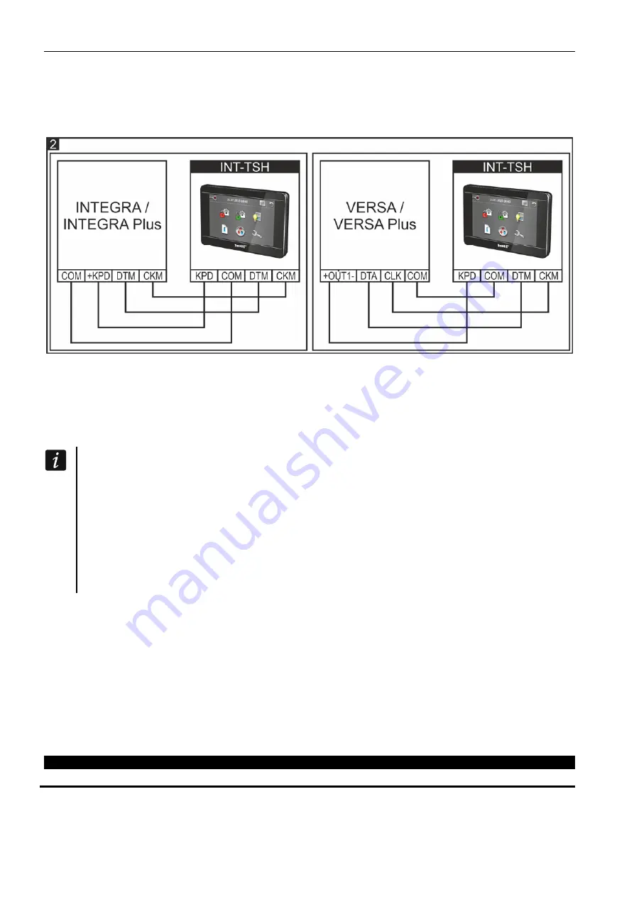
8. Connect the DTM, CKM and COM keypad terminals to the appropriate terminals of the control
panel communication bus (Fig. 2). It is recommended that the unshielded non-twisted cable be
used for making the connection. If you use the twisted-pair type of cable, remember that CKM
(clock) and DTM (data) signals must not be sent through one twisted-pair cable. The wires must
be run in one cable. The length of cables must not exceed 300 m.
9. Connect the wires to the terminals of additional zones, if any detectors are to be connected to
them (the detectors are to be connected in the same way as to the control panel onboard zones).
The zones are supported when the keypad is connected to INTEGRA / INTEGRA Plus control
panel.
10. Connect the supply wires to the KPD and COM terminals. The keypad can be powered directly
from the control panel, from expander with power supply or from a power supply unit.
If the keypad is to be powered directly from the control panel, the keypad KPD terminal:
INTEGRA
64 / INTEGRA
128 / INTEGRA
64
Plus / INTEGRA
128
Plus /
INTEGRA 256 Plus: can be connected to the +KPD terminal of the control panel,
INTEGRA 24 / INTEGRA 32 / INTEGRA 128-WRL: should be connected to the OUT1 or
OUT2 terminal of the control panel (only high-current outputs have a sufficient current rating
– program the output type as 41.
P
OWER SUPPLY
),
VERSA 5 / VERSA 10 / VERSA 15 / VERSA Plus / VERSA IP: should be connected to the
“+” terminal of OUT1 or OUT2 high-current output of the control panel (only high-current
outputs have a sufficient current rating).
11. Place the front panel onto the catches, snap close the enclosure.
Description of terminals
KPD
- power supply input.
COM
-
common
ground.
DTM
-
data.
CKM
-
clock.
Z1, Z2
-
zones.
RSA, RSB
- terminals provided for future applications (RS-485).
The declaration of conformity may be consulted at www.satel.eu/ce
SATEL sp. z o.o. • ul. Budowlanych 66 • 80-298 Gda
ń
sk • POLAND
tel. 58 320 94 00
www.satel.eu


