14
Installer Manual
SATEL
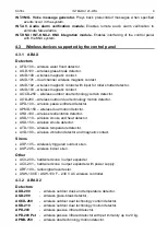
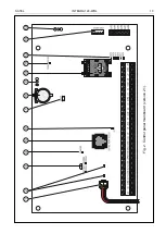
GSM STATUS LED indicating the communicator and cellular network status:
−
OFF – the communicator disabled,
−
ON – outgoing voice call,
−
lit, getting dimmed every 0.5 second – incoming voice call,
−
flashing slowly – CSD communication,
−
flashing rapidly – GPRS communication
−
1, 2, 3 or 4 flashes every 2 seconds – communicator standby mode (the number of
flashes indicates the cellular signal level).
LEDs indicating the status of low-current outputs.
socket for connecting the INT-VG voice module, INT-AV audio alarm verification
module, CA-64 SM voice synthesizer expander or SM-2 synthesizer.
socket for GSM/GPRS communication antenna.
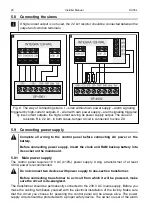
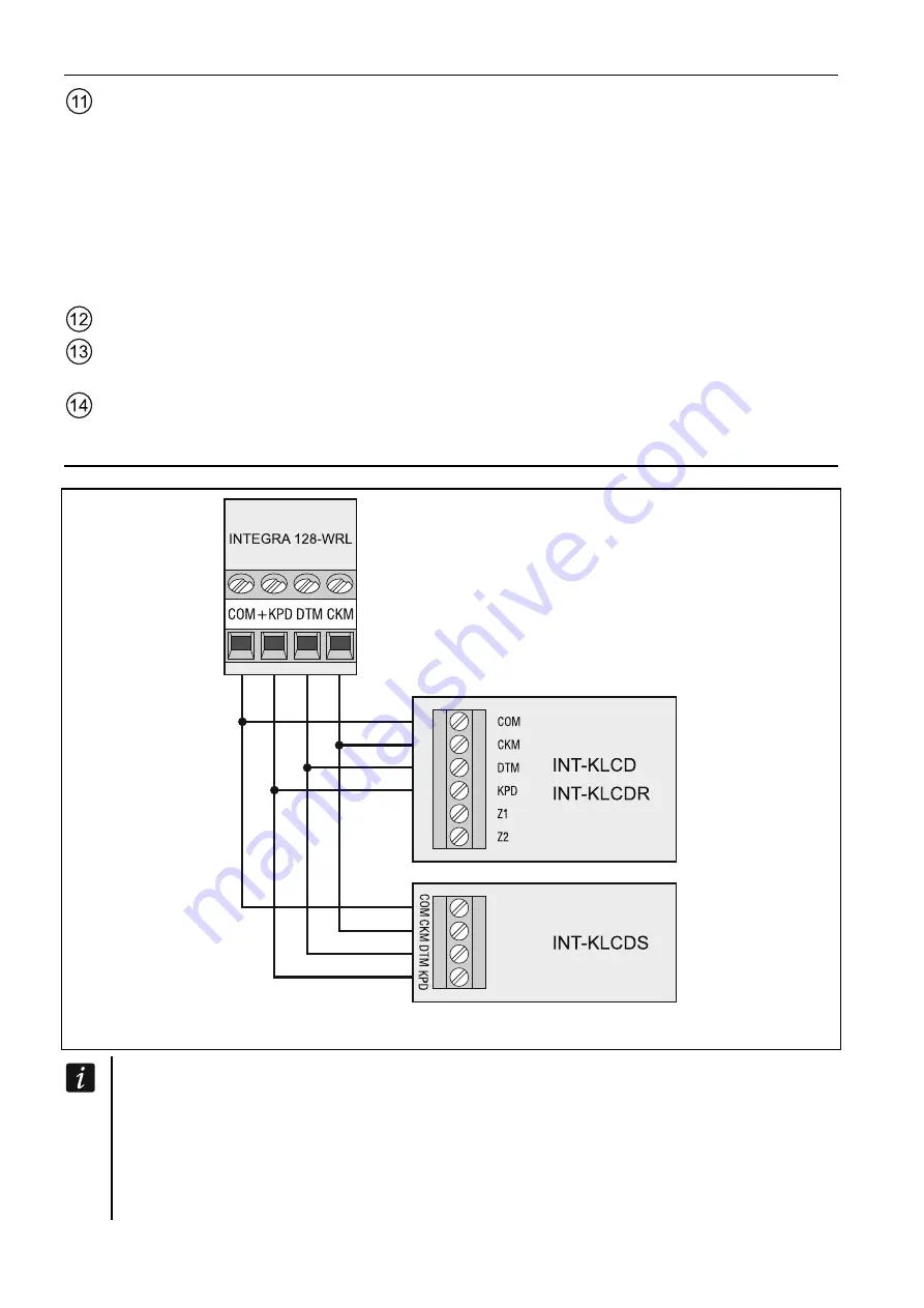
5.5 Connecting devices to the keypad bus
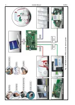
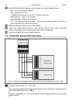
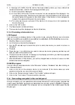
Fig. 3. Connection of keypads (other devices should be connected in a similar way).
The bus wires must be run in one cable.
The distance between the keypad (or other device to be connected to keypad bus) and
the control panel may be up to 300 m.
Devices installed far from the control panel may be supplied locally from a separate
power source.

