5.1
RS-232 Interface
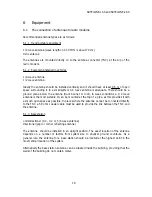
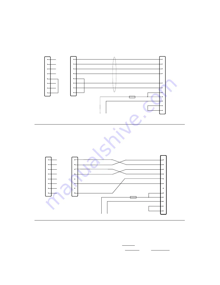
The radio modem is connected to terminal via RS-232 interface. A typical connection
where all handshaking lines are used is according to the figure below.
TD
RD
RTS
CTS
SGND
CD
DTR
+Vb
GND
11
9
13
6
7
2
1
15
8
+Vb GND
Radio modem
FUSE 630 mA slow
3
4
TD
RD
RTS
CTS
CD
2
3
4
5
7
8
25-PIN D-CONNECTOR
DTR
20
DSR
6
SGND
TD
RD
RTS
CTS
CD
2
3
5
1
7
8
9-PIN D-CONNECTOR
DTR
4
DSR
6
SGND
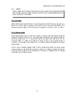
In some systems the radio modem is connected to another data transmission equipment
(modem). The lines should in this case be connected across according to the picture below.
TD
RD
RTS
CTS
CD
2
3
4
5
7
8
TD
RD
RTS
CTS
SGND
CD
DTR
+Vb
GND
11
9
13
6
7
2
1
15
8
+Vb GND
Radio modem
FUSE 630 mA slow
DTR
20
DSR
6
SGND
3
4
DSR
10
TD
RD
RTS
CTS
CD
2
3
5
1
7
8
9-PIN D-CONNECTOR
DTR
4
DSR
6
SGND
25-PIN D-CONNECTOR
5.2
Supply of current
The nominal voltage of SATELLINE radio modems is 12 V. The range of voltage is 10 - 14
V. Variations in the voltage below 1V are allowed as the radio modem is changing from
one mode to another. The operating voltage of the positive pole of the D 15 connector is
connected to the pins of the D connector and to the negative poles 7 and 8. The DTR
line in position "1" can be used as an ON/OFF switch. In this case the logical state "1"
(+5...+12 V) corresponds to ON and "0" (0 V...-12 V) to OFF.
SATELLINE-1AS and SATELLINE-2AS
14


