S
E
TTING
Manual Datalogger SenNet DL150 / DL151 / DL170 / DL171 / DL172
Versión 1.01
Satel Spain
51
14.
MENU
“
INTERNAL METERS
”
ABC METHOD
The DL151, DL171 and DL172 models incorporate a function to check the correct connection of
voltages and currents, called ABC METHOD.
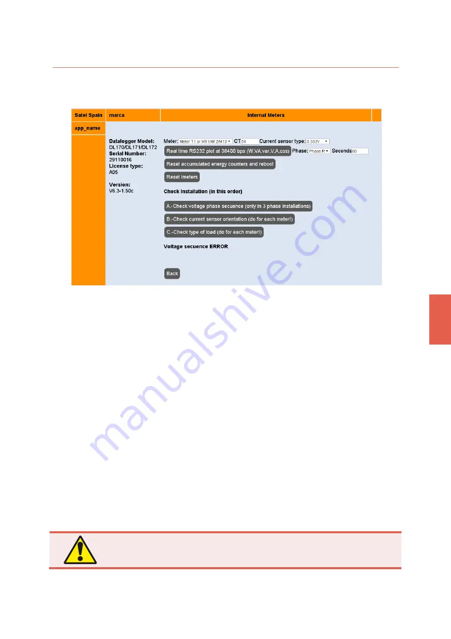
Figure 26. Overview of the menu
Internal Meters
, used to apply the ABC method to check the
connection of the internal electricity meters.
For
each meter
you want
to
check, you must follow the following steps:
▪
Meter:
to select the meter.
▪
CT:
to select the current of the current transformer /Rogowski coil.
▪
Current sensor
type:
the type of sensor can be 0,333V or Rogowski coil.
▪
Reset accumulated energy counters and
reboot.
To reset the readings. It is important to perform
this operation:
o
Whenever the installation is completed
o
When the datalogger is moved to different facilities
▪
Reset imeters
. To reset
the counters after making any configuration changes (current
transformers...).
Then the ABC steps should be followed.
▪
A, check the voltage phase sequence
.
To test the phases. It is done only once and allows you to
check in three-phase installations that connection to voltage phase sequence R, S, T has been
respected. Do not pass to step B until the configuration of this step is correct.
You should see
the message:
Voltage sequence OK
To connect the phases correctly you can enlist the help of a phase meter. Usually, the colour
code that works on most installations is: Black for V1 (R) phase, brown for V2 (S) and grey for
V3 (T). The phase V0 (N) is usually blue. However, such classification sometimes fails.
After
making a change in the configuration of the installation, you must press
reset imeters
before
pressing again
A. - Check voltage phase sequence
.
Do not go to Step B if you do not see the message "Voltage sequence OK"
as a result of step A
Summary of Contents for SENNET DL150
Page 1: ...Dataloggers series Device network DL150 DL151 DL170 DL171 DL172 ...
Page 8: ......
Page 44: ......
Page 86: ......


