SPL-2010
SATEL
3
INTEGRA 32
SPL-2010
SO
TMP
SA
+
+
OUT1
COM
COM
COM
Z1
OUT2
COM OUT1 COM
COM
COM
COM
OUT2
+KPD DTM CKM
+EX
CK
AUX
Z1
DT
R
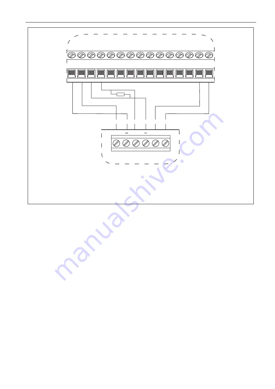
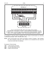
Fig. 3. Connecting the SPL-2010 siren to high-current outputs
of INTEGRA 32 control panel. The OUT1 output will release optical signaling, and
the OUT2 output – acoustic (high-current outputs with normal polarization - activated
when +12 V voltage is supplied). The Z1 zone is programmed as 24 h tamper.
It is possible to control two types of signaling from one output of control panel, by connecting
in parallel the terSA to +SO and -SA to –SO.
Note:
Some control panels may require connecting a resistor R (approx. 1 kΩ)
between
the +SA- terminals in the siren
. If this resistor is not connected, the siren may emit
some low sounds when not alarming.
Description of the terminals:
+SO-
– optical signaling terminals
+SA-
– acoustic signaling terminals
TMP
– tamper circuit terminals


