®
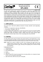
OPTICAL-ACOUSTIC
SIGNALING DEVICE
SPL-2030
spl2030_en 09/08
The SPL-2030 optical-acoustic signaling device (siren) is designed for application in the
burglary and assault signaling systems. The signaling function is performed in two ways:
visually (by blinking of indicator LEDs situated in the lower part of the enclosure) and
acoustically (by a modulated high-volume sound signal). As the light source, a set of LEDs is
used, whereas the sound signal is generated by means of a piezoelectric transducer. Design
of the signaling device housing ensures a high degree of tamper protection (against opening
and/or tearing off from the base). The electronic circuit is made by the use of SMD technique
and impregnated against the adverse influence of weather conditions, which ensures a high
reliability of the device. As the SPL-2030 external housing is made of the PC LEXAN
high-impact polycarbonate, it is characterized by a very high mechanical strength, and a nice
appearance of the device is guaranteed even after many years of service.
1. Outfit options
The siren can be fitted with additional elements of tamper protection (sold separately),
including:
•
inner cover of galvanized metal sheet, OM-SPL2000,
•
foam detector, SPL-SAB or SPL-TO.
In order to install the SPL-SAB detector, remove the electronics board and unsolder the SMD
component (situated underneath the board), designed for shorting the solder points J3
and J4. Next, solder the detector leads to these points and, using a screw, attach
the detector to the siren base (so as to cover the opening) and remount the PCB.
2. Installing
The SPL-2030 siren should be mounted on flat vertical surface in inaccessible place in order
to minimize tampering possibility. It must be attached to the surface by means of screws and
expansion plugs (the screws and expansion plugs are included in the device delivery set).
Note:
Make sure to leave a distance of about 4.5 cm between the upper edge of the
signaling device base and the ceiling or another object which limits the mounting
position from above. With no gap, mounting of the signaling device external housing
may be difficult.
Explanations for Figure 1:
1 – mounting holes
2 – auxiliary opening
3 – foam detector (option)
4 – buzzer
5 – cable hole
6 – tamper element “
S
” (should be screwed to the mounting surface; do not apply excessive
force, so as not to break the narrowings)
7 – water drain holes (make sure they are not stopped)


