SATEL SPL-2030
3
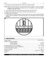
7. Connect the siren terminals with wires to the control panel terminals.
Note:
Some alarm control panels may require that a resistor R (approx. 1 k
Ω
) be connected
between the +SA- terminals in the siren (see Fig. 3). Otherwise, the siren will produce
a buzzing sound when inactive.
8. Use jumpers to select the tone which will be used by the siren (see: Fig. 2).
9. Replace the siren cover, close the cover and then lock it with the screw.
10. Power on the control panel.
11. Test the siren for correct functioning. In order to test the siren you can use the output test
function, which is available in some control panels, or you can trigger an alarm for testing
purposes.
4. Specifications
Supply voltage ................................................................................................... 12 V DC ±15%
Maximum current consumption:
optical signaling ..........................................................................................30 mA
acoustic signaling .....................................................................................180 mA
Sound pressure level (at 1 m distance) .................................................................up to 120 dB
Environmental class according to EN50130-5 ........................................................................ III
Operating temperature range..................................................................................-35...+55 °C
Maximum humidity.......................................................................................................... 93±3%
Dimensions ..................................................................................................298 x 197 x 90 mm
Weight............................................................................................................................... 725 g
The declaration of conformity may be consulted at www.satel.eu/ce


