SATEL
SPLZ-1011
2
After installing the siren, it is recommended to seal the mounting holes and the cable entry
with silicone compound.
3.
Operation of siren
The way of activating the SPLZ-1011 is different from that of the SPLZ1010B siren
(read carefully the text below).
The SPLZ-1011 can operate with any source of alarm signal. The circuits for acoustic and
visual signaling have separate control inputs. The acoustic signaling is controlled by the STA
input, while the visual signaling – by the STO input. Signaling is triggered after a change of
voltage polarity from 0V to 12V or from 12V to 0V.
Note: Alarm will be triggered also in case of stable signal loss at control input, e.g. after
cutting off the cable.
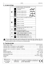
The way of changing voltage polarity for the purpose of triggering the alarm is set by means
of the jumpers PLA and PLO.
The siren has been designed so as to be inactive on connecting power supply to it,
irrespective of the status of inputs STA and STO. Only after elapse of 20 seconds in the
stable, inactive state (constant power supply from the control panel and voltage on inputs
which does not trigger alarm) it is possible to trigger the signaling. After each switching the
power supply off and on, the time is counted over again. This function allows an accidental
activation of the device to be avoided during installation of the system.
The test mode makes it possible to activate signaling without the need to wait for 20
seconds. In order to do so, remove the jumper O+A, switch the siren on and, within 5
seconds, put the jumper on again.
The SAB terminals are used for connecting the siren to the tamper circuit of the alarm
system. When the siren is correctly mounted and the contacts of onboard switches are
closed, the SAB terminals are shorted, too.
The siren is adapted for operation with a 6 V battery installed (back-up power supply).
The external power supply should be connected to the terminals +12V and GND. The loss of
voltage on these terminals will trigger a tamper alarm, the duration of which depends on the
settings of jumpers TM0 and TM1. The kind of signaling is set with the jumper O+A.
Restoration of the supply voltage will cancel the tamper alarm. Having mounted the siren,
check the performance of this function by disconnecting and reconnecting the power supply
voltage.
Note: The jumpers TM0, TM1 determine the maximum active time of acoustic signaling.
Afterwards, irrespective of the value set on the control panel, the siren will go silent.
Signaling can only be triggered again after the STA input voltage returns to the state
corresponding to the PLA jumper "no alarm" setting.
The LED placed on electronics board blinks when the +12V input power voltage is applied.
The LED can be switched off by removing the JP8 jumper.
4. Connection
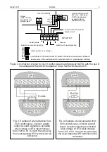
There are two types of alarm outputs which are used in alarm control systems: common
ground outputs and common supply outputs. The siren can be activated by any type of
output, provided that suitable connections are made. If the control panel alarm outputs have
no resistors
which induced polarization,
then, in order to ensure proper operation of the
device, it is necessary to connect 2,2k
Ω
resistors as shown on figure 2, 3 or 4 (depending on
the output type). They can be connected in the control panel or in the siren.
Such resistors must also be connected for outputs with load control.


