SATEL
3
4. Installation and Connection
•
The siren may only be used indoor.
•
The siren should be installed on a flat surface by means of screws and expansion bolts.
•
All connections should only be made after the alarm system power supply has been
disconnected.
•
Install the battery inside the siren only after all installation work is completed and the
alarm system power supply turned on. If the battery is installed before the external power
supply is turned on, alarm will be triggered.
OUTx COM OUTy Zx COM
SPW-250
+12V
TMP TMP D COM
CONTROL PANEL
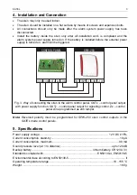
Fig. 3. Way of connecting the siren to the alarm control panel. OUTx – control panel output
with power supply function. OUTy – control panel output for signaling control. Zx – control
panel zone programmed as 24h tamper.
Note:
Reversed polarity must be programmed for SPW-250 siren control outputs in the
SATEL made control panels.
5. Specifications
Power supply voltage......................................................................................... 12 V DC ±15%
Current consumption, stand-by.........................................................................................10 µA
Current consumption, maximum ......................................................................................90 mA
Sound pressure level (at 1 m distance) .................................................................up to 120 dB
Backup battery............................................................................... lithium battery, CR123A 3 V
Standards complied with......................................................................EN50130-4, EN50130-5
Environmental class according to EN50130-5 ......................................................................... II
Operating temperature range..................................................................................-10...+55 °C
Weight............................................................................................................................... 160 g


