background image

7. Front Panel Controls 


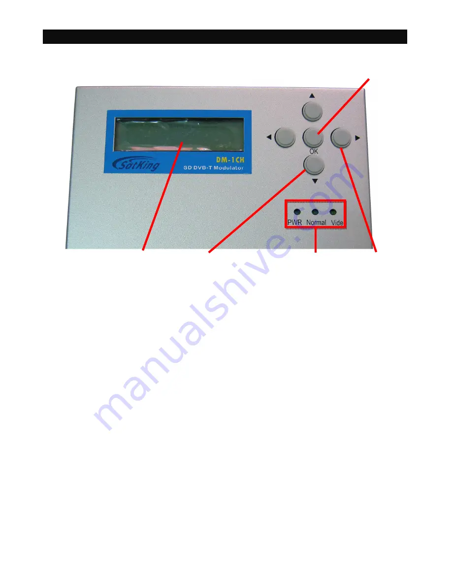
F1: LCD Display - This display presents the selected menu screen and the parameter settings. 
The backlight in the display is on when power is applied. 

F2: LED – These lights indicate the status, which from left to right is power, normal and video. 

F3:  Left  and  Right  Buttons  –  Use  the  left  and  right  arrow  buttons  to  navigate  from  screen  to 
screen  to  view  a  parameter  setting  within  a  particular  program  group.  These  buttons  are 
operational in the view mode or the program mode. Using only these buttons will not change any 
parameter setting. 

F4: Up and Down Buttons – Use the up and down arrow buttons to change the value of a viewed 
parameter setting. The unit must be in the program mode in order for these buttons to become 
active for changing a parameter setting.   

F5: OK Button - Use the ENTER button to enter the program mode or to save and load a new 
setting or settings after adjustment. Hold for approximately 2 seconds until the bottom line of the 
display starts to flash to enter the program mode. After entering the program mode, momentarily 
pressing the OK button again will load and save any settings that may have been changed using 
the Up and Down buttons. 


F1


F2 

F4


F3


F5


Summary of Contents for DM-1CH

Page 1: ...DM 1CH SD DVB T MODULATOR INSTRUCTION MANUAL...

Page 2: ...f contents 3 Important Safety Instructions 4 Important Safety Instructions Cont 5 Specification 6 General Description Features 7 Front Panel Control 8 Rear Panel Connections 9 Software Flow Chart 10 S...

Page 3: ...nding or Polarization This product may be equipped with a polarized alternating current line plug a plug having one blade wider than the other This plug will fit into the power outlet only one way Thi...

Page 4: ...are covered by the operating instructions as an improper adjustment of other controls may result in damage and will often require extensive work by a qualified technician to restore the product to its...

Page 5: ...6 7 8 MHz Carriers 2K 8K Constellation QPSK 16QAM 64QAM Guard Interval 1 4 1 8 1 16 1 32 Code Rate 1 2 2 3 3 4 5 6 7 8 Frequency Range 50 860 MHz Output Level 75 90dBuV Modulator Modulator Modulator...

Page 6: ...audio PCR PID User friendly setup and control Compact and wall mountable DM 1CH is a composite video input standard definition DVB T modulator which provides COFDM RF signal in range of 50 860MHz It i...

Page 7: ...only these buttons will not change any parameter setting F4 Up and Down Buttons Use the up and down arrow buttons to change the value of a viewed parameter setting The unit must be in the program mod...

Page 8: ...Out 50 860MHz channel frequency 75 90dBuV output level ANT In Terrestrial Digital signal input Video Interface CVBS Composited video input supports NTSC and PAL Audio Interface Stereo Left Left audio...

Page 9: ...9 Software Flow Chart...

Page 10: ...10 Software Flow Chart Cont...

Page 11: ...11 Australia Television Frequencies Channels MHz...

Page 12: ...2 7 46 8 29 8 78 9 04 8 70 9 67 10 24 10 55 9 95 11 06 11 71 12 06 2 3 9 95 11 05 11 70 12 06 11 61 12 90 13 66 14 07 13 27 14 75 15 61 16 09 3 4 11 19 12 44 13 17 13 57 13 06 14 51 15 36 15 83 14 93...

Reviews: