background image

INSTALLATION (continued) 

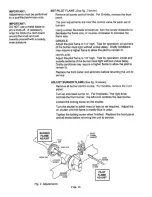
SET GAS PRESSURE: 
Gas pressure regulator is factory set. 
SET PILOT FLAME: 
Remove all burner control knobs, then remove the front panel.


The 

pilot adjustments are near the control valve for each set of


burners. 

Using a small, flat-blade screwdriver, turn the screw clockwise to


decrease the flame size, or counter-clockwise to increase the


flame size. 
Adjust the pilot flame to 1/4” high. Test for operation: all sections


of the burner must light without undue delay. Drafty conditions


may require a higher flame to allow the pilot to remain lit.


Replace the front panel and all knobs before returning the unit to


service. 
ADJUST BURNER FLAME: 

Remove all burner control knobs, then remove the front panel.


Turn an individual burner on. 
Loosen the locking screw on the shutter. 

Turn the shutter to admit more or less air as required. Adjust the


air shutter until the flame is mostly blue in color. 
Tighten the locking screw when finished. Replace the front panel


and all knobs before returning the unit to service. 


IMPORTANT: 

Adjustments must be performed


by a qualified technician only.


IMPORTANT: 
This griddle is shipped from 
the factory equipped for either:


natural gas and adjusted for 
sea level to 2000 feet elevation;


or, propane (LP) gas and 
adjusted for sea level to 5000 
feet elevation. 

For operation other than listed


above, contact your manufacturer 


IN

S

T

A

L

L

A

T

IO

N

 (C

o

n

tin

u

ed

Page 8 

Summary of Contents for ESG-24

Page 1: ...Instructions to be followed in the event the user smells gas fumes must be posted in a prominent location in the installed kitchen area The information shall be obtained from a local gas supplier WAR...

Page 2: ...f this price list does not constitute an agree ment or offer to sell product to the possessor Prices are subject to change without notice Prices do not include sales tax All prices are in U S dollars...

Page 3: ...nspection Manufactuer cannot assume liability for damage or loss incurred in transit We will however at your request supply you with the necessary documents to support your claim TABLE OF CONTENTS WAR...

Page 4: ...3 FEATURES OPERATING CONTROLS ADJUSTABLE LEG BURNER ASSEMBLIES PILOT LIGHTS PILOT ADJUSTMENT CONTROL VALVE TYPICAL Fig 1 Medium Duty Gas Griddle Features Operating Controls FEATURES AND OPERATING CONT...

Page 5: ...the supplied 4 legs properly installed Do not operate this appliance if the smell of gas is present Turn off all gas supply valves and move to a remote location to call your manufacturer for service...

Page 6: ...NOTICE Manufacturer s warranty on this griddle is in effect only when the griddle is installed in accordance with these instructions and local codes and ordinances or in the absence of local codes th...

Page 7: ...e gas supply line used to connect the griddle to the gas supply system must be black iron pipe or other material as approved by local ordinance for gas piping 2 Gas supply piping must be inside 3 4 di...

Page 8: ...e shut off valve must be installed between the gas supply piping and the gas pressure regulator Shut off valves moisture trap and all associated piping must be supplied by the gas piping installer It...

Page 9: ...bs before returning the unit to service ADJUST BURNER FLAME Remove all burner control knobs then remove the front panel Turn an individual burner on Loosen the locking screw on the shutter Turn the sh...

Page 10: ...o smell near floor level because some gas is heavier than air and will settle to the floor For initial startup and any time the gas supply has been shut off it may take several minutes to light the pi...

Page 11: ...s from OFF to ON The right knob controls the front burner The left knob controls the rear burner Light the burner by turning the control knob to the ON position until fire forms completely around the...

Page 12: ...thoroughly cleaned Using a scraper remove all grease and food waste from the grease trough by pushing it down the waste hole and into the grease tray 6 After scraping all cooking waste from grease tro...

Page 13: ...rior surfaces dry with a soft clean cloth Allow burners to air dry so that interior passages are completely free of water Examine burners to be sure the air shutters are in their proper position Reins...

Page 14: ...internal component Contact manufacturer for repairs Pilot will not light Gas supply off Check main unit gas valves Air in lines Turn pilot valve on Attempt to light pilot every 15 sec Pilot valve not...

Page 15: ...information available if calling for service RESTAURANT______________________________ LOCATION _______________ INSTALLATION DATE _________________________ TECHNICIAN______________ SERVICE COMPANY ____...

Page 16: ...Page 15...

Page 17: ...Page 16...

Reviews: