background image

Service and Installation Manual                                         


OPERATION                                                                                                                                               


Do not throw items into the storage area. Failure to heed these recommendations could result in damage to 

the interior of the cabinet.


Refrigerated cabinets 

Temperature range for the internal cabinets is 28° F to 50° F for all food prep, undercounter and worktop 
refrigerator units; and -11° F to -1° F for undercounter and worktop freezers.     
Food Prep units should operate with pans in place. Operating without pans and/or pan covers in place 
will decrease the efficiency and may damage the unit due to continuous running. 

Continuous opening and closing of the door will prevent the unit’s ability to maintain optimum refrigeration 
temperature. 

Top section is not intended for overnight storage. Product should be removed from pans. Pans can 
remain in cabinet while empty. 

Defrosting:   

Every 6 hours, the unit will turn off to let the ice on the evaporator coil clear up. The control will display the 
defrost symbol. When the coil temperature reaches the terminal temperature or after 20 minutes 
(whichever comes first), the unit will turn on again.


On/Off Switch: 

An on/off switch is located on the front of the bottom panel and on the condenser compartment door for the 
Pizza prep tables. When the unit is on, the switch will glow green. 

 
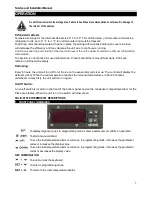
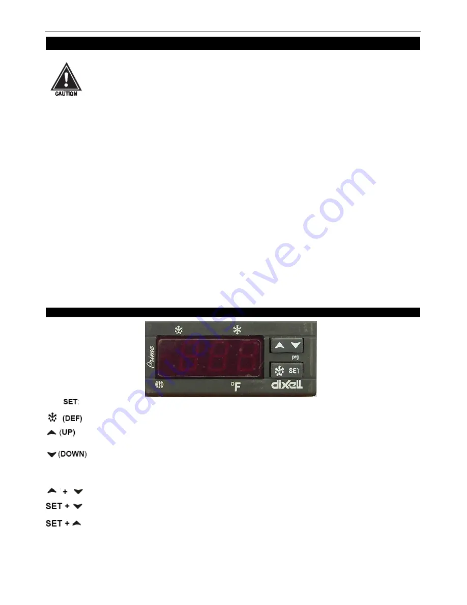
SOLID-STATE THERMOSTAT DESCRIPTIONS 

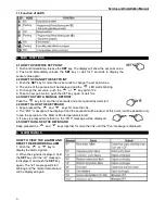
1.    FRONT PANEL COMMANDS                                                                                                                                                                                                         


To display target set point. In programming mode, select a parameter or confirm an operation. 

To start a manual defrost 

To see the last temperature alarm occurrence. In programming mode, it browses the parameter                       

codes or increases the display value 

To see the last temperature alarm occurrence. In programming mode, it browses the parameter                   

codes or decreases the display value 

KEY COMBINATION 

To lock & unlock the keyboard 

To enter in programming mode 

To return to the room temperature display 


Summary of Contents for PUC28F

Page 1: ...ervice Installation and Care Manual Please read this manual completely before attempting to install or operate this equipment Notify carrier of damage Inspect all components immediately See page 2 IMP...

Page 2: ...uring unloading so the equipment is not damaged while being moved into the building 1 Visually inspect the exterior of the package and skid or container Any damage should be noted and reported to the...

Page 3: ...ervice and Installation Manual 3 SPECIFICATION MODEL V Hz Ph AMPS STORAGE CAPACITY Cu ft HP SHELF CAPACITY Sq ft BTU CHARGE OZ SHIP WEIGHT LBS NEMA PLUG PUC28F 115 60 1 7 6 5 1 2 14 3500 12 3 291 5 15...

Page 4: ...er because the doors will line up with the frames properly the cabinet will not be subject to undue strain and the contents of the cabinet will not move around on the shelves Use a level to make sure...

Page 5: ...Defrosting Every 6 hours the unit will turn off to let the ice on the evaporator coil clear up The control will display the defrost symbol When the coil temperature reaches the terminal temperature o...

Page 6: ...ROST Push the key for more than 2 seconds and a manual defrost will start 2 4 HOW TO LOCK THE KEYBOARD 1 Keep pressed the and keys for more than 3s 2 The POF message will be displayed and the keyboard...

Page 7: ...condenser coil can initially cause high temperatures and excessive run times Continuous operation with dirty or clogged condenser coils can result in compressor failures Neglecting the condenser coil...

Page 8: ...r seals Also never use sharp tools or knives to scrape or clean the gasket which could possibly tear the gasket and rip the bellows Gaskets can easily be replaced and don t require the use of tools or...

Page 9: ...Service and Installation Manual 9 WIRING DIAGRAM MODEL PUC28F...

Page 10: ...Service and Installation Manual 10 WIRING DIAGRAM MODEL PUC28F...

Reviews: