Planning, transport, installation
LASERTEC 40
Page 49
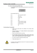
Connection for data exchange (SUB-D plug)
The plug SUB-D 9 pol. for data monitoring is located at the rear side of the
cooling plant.
Plug allocation Signal exit
Pin 1
Alarm Temperature Alarm
Pin 2
Alarm Flow
Pin 3
Remote start
Pin 4
+24V
Pin 5
GND
Pin 6
Collective failure message
Pin 7
Collective failure message
Pin 8
Water level alarm
Pin 9
NC
Commissioning of Cooling Plant
•
Switch on the power switch. The indication of the cooling control
shows ”OFF”.
•
Press the ”Standby” key. The display indicates the actual temperature
and failure messages.
•
Water level and water alarm are pending.
•
Now refill water through the filling opening on the front side of the
cooler. The light diode Water level warning (yellow) fades first. Refill
water until also the light diode Water level alarm disappears.
•
The cooler is ready for operation and starts cooling.
•
Filling capacity approx. 30 l.
For start-up must be preparated a minimum 30 l de-ionized water with the
conductivity of < 2,5 µS.

