Planning, transport, installation
LASERTEC 40
Page 57
Cooling plant (for the design water-air cooler only)
•
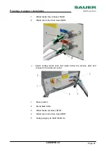
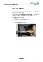
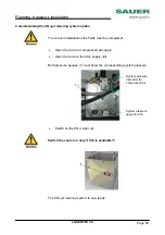
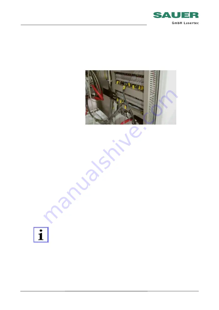
Guide cable with terminal strip from cooling plant from underneath
into the control cubicle and plug into terminal ”X 310” and X 301
(check for marking on the control cubicle).
•
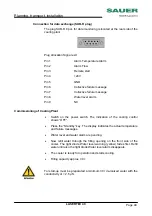
Plug in data cable (serial) with 9 pole plug (from machine) into cooling
plant and tighten screws (see ”connection water-air cooler).
Check
connection
Prior to switching on, check for correct connection. During this process
follow the list of points below and tick them off.
Check the mains connection in the switch cabinet using a meter for:
•
Correct
voltage,
•
Correct
frequency,
•
Clockwise rotating field,
•
Correct connection of the neutral conductor in the customer's supply
If all connections are correct, close the switch cabinet.
•
Once assembly is complete and the final inspection has been
performed, the machine can be switched on (see section
"Operation").
Electrical connection of data interfaces
•
On connecting the data interfaces (e.g. Ethernet), attention is to be
paid to ensuring the data cable is laid by the shortest route to the
interface on the control system (cable laying similar to measuring
system wires). Under no circumstances lay past the drive units for the
NC axes in the switch cabinet (EMC problems).
•
Pay attention to correct equipotential bonding between machine and
PC. Otherwise, correct transfer will not be possible.

