background image

15

STEAMCORE 

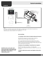
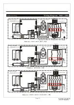
1.) Under NO circumstances is the steam line from the steam generator to
be restricted or reduced to less then 1/2” inside diameter, or contain a
steam trap. Steam line distance maximum 50 ft.

2.) Under NO circumstance should there be a valve or other obstruction in
the steam line.

3.) Water MUST be able to drain from all sections of the steam line at all
times.

4.) Adequately treat impure water or warranty policy may become null and
void.

5.) The steam generator MUST be positioned so that THE STEAM LINE
COMES O

OUT O

OF T

THE T

TOP.

6.) Use only factory supplied modular connector with any unit, any
substitute connector will void warrenty.

7.) Cutting or tampering with internal wiring will void warranty.

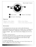
8.) Timer switch may not automatically turn on appliance if knob is not first
rotated past  “turn past” point ( “dot” above 5 minute mark) on the
mechanical timer switch.

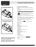
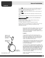
General Installation

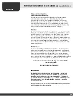
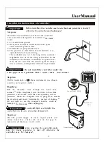
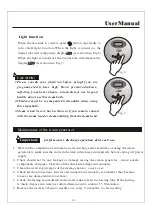
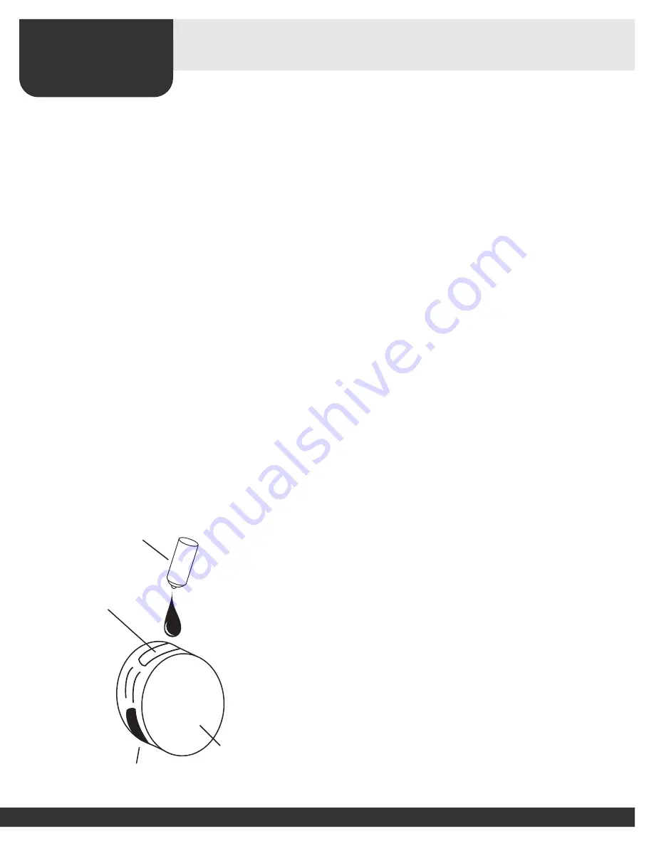
Enjoy Aroma essential oils by placing a drop or two into your 
steamhead as shown in the attached illustration. Only use 
Steamcore Aroma Essential Oils in a Steamcore steam 
head, or any other equivalent oil deemed suitable for use in 
the Steamcore steamhead.

Caution:

• Use essential oils with caution. Essential oils are for 
external use only. Keep out of reach of children. Essential 
oils are higly concentrated and are potent substances and 
should not be applied directly to the skin as they can be 
irritants. Use essential oils with caution.

• Place the drops into the steam head recess prior to turning 
on the steambath. Do not place drops in a hot steam head 
as SERIOUS INJURY CAN RESULT IF YOU DO NOT 
FOLLOW THIS WARNING.

• Start with one drop to gauge strength and suitability. Limit 
to a maximum of a few drops during a steambathing session. 
Some people may find that the aroma makes them dizzy and 
the user should exit the steam bath aIMMEDIATELY. If skin 
iffitation occurs stop using the oils immediatly. Remove any 
excess oil by washing in mild soap and water. If ingested, 
rinse mouth with water. Administer water or milk to dilute. 
Contact a physician immediately.

Tightly close containers when storing oils. Keep away from 
sources of ignition.

ELEGANCE 
STEAMHEAD

RECESS FOR
ESSENTIAL OIL

AROMA 10 ML
BOTTLE WITH
INTEGRATED
DROPPER

STEAM EMISSION SLOT

Summary of Contents for KWS 10.5

Page 1: ...ATOR SAUNACORE INSTALLATION INSTRUCTIONS FOR STEAMCORE STEAM GENERATORS CONTROLS INSTALLATION GUIDE OWNERS MANUAL SAUNACORE www saunacore com This Manual contains installation and operation instructio...

Page 2: ...51 6662 Inspection and Shipping Claim Check for shipping damage upon receipt of the product Saunacore is not responsible for damage to the product sustained during shipping If damage is evident before...

Page 3: ...ter filter is recommended 9 Make sure water is turned on to the unit before testing or operating the unit 10 Unit and Supply lines MUST be protected from freezing Parts Enclosed Control Steamhead Stea...

Page 4: ...ce to be performed by qualified electricians and plumbers only Installation or service by unqualified persons may void the warranty Installation Instructions Pressure Safety Valve s Supplied Only must...

Page 5: ...ate to accumulate 8 All inside surfaces should be adequately sealed Around faucets shower head and steam heads should be sealed with mildew resistant silicone 9 Ceiling height should be no higher than...

Page 6: ...located outside the steamroom a remote sensor is required for all controls 12 Install anti water hammer device as required 13 Provide access to both ends of the steambath generator for servicing Stea...

Page 7: ...units 1 Check power voltage Most homes have 240V IPH service 2 Use minimum 90 deg C 300V copper conductors only sized in accordance with National and Local electrical codes 3 Connect equipment ground...

Page 8: ...ower steam room When connecting you must use the two wrench method or you may break the seal on the connection between the drain pipe and the boiler tank and cause leakage Testing Now that your Steamc...

Page 9: ...h will help extend the life and minimize maintenance schedules of the steam bath generator Maintenance Saunacore steambath generators are designed for unattended operation and require little maintenan...

Page 10: ...he way from the steam generator to the waste outlet Under certain conditions it may be necessary to place the steam generator on the wall brackets or a stand to achieve the right angle Cleaning the St...

Page 11: ...ong as you feel comfortable After your last spell amongst the clouds of steam you ll find a long cool shower a real delight Let your body dry off naturally before putting your clothes on Relax treat y...

Page 12: ...ply Air Gap Drain 1 or 1 2 Steam Line Outlet 1 Steam LIne 1 1 2 Pipe Slope Down Floor Drain 1 Water supply Typical Residential Plumbing Installation ELEGANCE STEAM HEAD INSTALLATION 3 4 NPT Female mad...

Page 13: ...ure 1 2 pipe slope down Two Elegance Steam Heads Water supply 1 or 3 4 Steam Line KWS 9 KWS 18 Commercial Plumbing Installation with Elegance Steam Head s KWS 22 5 KWS 36 Commercial Plumbing Installat...

Page 14: ...e silicone or tape sealant when threading onto st prevent steam leaks for connections A 15 p s i Pressure Relief Safety Valve and coupling has been supplied with your steam generator unit It must be i...

Page 15: ...e Aroma Essential Oils in a Steamcore steam head or any other equivalent oil deemed suitable for use in the Steamcore steamhead Caution Use essential oils with caution Essential oils are for external...

Page 16: ...ide the steambath enclosure according to personal preference It is recommended that the SSI Control is located about 4 to 5 feet above the floor The control should be located away from direct shower s...

Page 17: ...17 User Manual Control panel both SSI and SSII dimension 113mm 25mm 75mm SSI and SSII Control panel may be switched for Spa II SS I SS I I 160mm 120mm 23mm 70mm...

Page 18: ...Important Do not install the controller under the water pipe or in a position where water comes into contact Step two Drill a round hole of 35mm in diameter in a chosen position no larger or smaller...

Page 19: ...ig 2 5 Let the temperature sensor go through the back of the sensor holder As shown in Fig 3 6 The temperature sensor should be installed by extending about 1cm from the front of the room to make sure...

Page 20: ...Adjust Key LOW Steam Time Adjust Key HIGH 2 9 3 2 8 2 4 7 6 6 Power ON OFF When unit is powered on power indicator LED should be lit Press and release button to activate system and all function button...

Page 21: ...eam time when system is activated Steam time LED screen shows set time from 1 99 minutes System shuts down power supply to heater elements automatically when desired steam time is over Use and buttons...

Page 22: ...t stop or pause in the preset time to keep the temperature in the set number ON OFF When it is electrified the system shuts off all the loads to remain in a waiting state and the digital tube will dis...

Page 23: ...ube will display normally current environment temperature When the system is started press button or when the steam function time is due the system will be shut 10 minutes after the system is shut off...

Page 24: ...shown in Fig 7 1 Wait for the completion of automatic water discharge after each time of using the steam generator to make sure the water in the tank is discharged completely before cutting off power...

Page 25: ...s ight s Page 25...

Page 26: ...Page 26...

Page 27: ...ck Long Pin Yellow Middle Pin Red Red Blue Brown Red Light G L1 L2 L3 Red Red J1 2 Red Red J1 1 Red Red J3 2 Red Red J2 To Control Panal Terminal Block J2 2 J1 1 J1 2 J3 1 J2 1 J3 2 J1 J2 J3 Yellow Gr...

Page 28: ...8V 1 57 7 208V 3 33 4 450V 3 15 4 575V 3 10 6 KWS 13 5 13500 625 240V 1 56 3 2 1 4 2 208V 1 64 9 208V 3 37 5 450V 3 17 3 575V 3 13 6 KWS 15 15000 685 208V 3 41 7 2 1 4 2 450V 3 17 3 575V 3 13 6 KWS 18...

Page 29: ...eam generat or Cause The contr ol panel is incorrectly set Solution Check the time and t emperature on the contr ol panel Cause The f ilter is clogged Solution R emove the filter which is placed in th...

Page 30: ...tween the control panel and the electrically controlled box has become loose and whether the power circuitry has good contact 2 Change a plugboard Water leakage 1 The water pipe connector becomes loos...

Page 31: ...year This cost will include 2 maintenance services per year for your Steamer including par ts repair s and labour _ _ _ _ _ _ _ _ _ _ _ _ _ _ _ _ _ _ _ _ _ _ _ _ _ _ _ _ _ _ _ _ _ _ _ _ _ _ _ _ _ _ _...

Reviews: