
WARNING! SEVERAL POWER SUPPLY. CHECK THAT THERE
IS NO CHARGE IN THE MACHINE BEFORE DOING ANY
MAINTENANCE WORK!
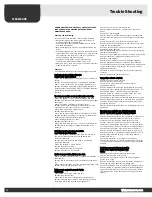
Checking and fault-finding.
In the e vent of faulty operation, f irst check the f ollowing:
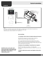
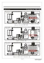
• are the contr ol panel and st eam generat or wired up in
accor dance with the wiring diagram?
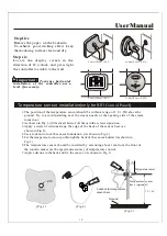
• is the st eam generat or correctly installed in accor dance
with these instructions?
• does the drainage pipe slope do wn pr operly t owards the
drain?
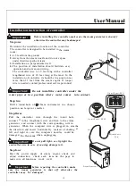
• is the f ilter clogged? The f ilter is locat ed at the point where
incoming w ater is fed into the generat or. T o clean the f ilter,
disconnect the f eed pipe, rinse it free fr om par ticles of
calcium carbonat e and o ther deposits.
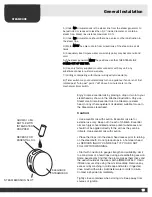
• are there an y sharp bends in the st eam pipe? (the
minimum permitt ed radius of bends is 50 mm, 2")
• If there is a tap on the w ater supply t o the st eam generat or,
make sure this is no t closed.
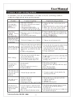
Checklist
with alternative causes of pr oblems and suggest ed actions.
L
Lo
ou
ud
d n
no
oiisse
ess iin
n tth
he
e ffe
ee
ed
d p
piip
pe
ess w
wh
he
en
n tth
he
e
sso
olle
en
no
oiid
d vva
allvve
e o
op
pe
en
nss o
orr ccllo
osse
ess..
Cause: The st eam generat or feed pipes are no t sufficiently
secure.
Solution: Fix the pipes securely t o the w all with pipe clips.
Cause: “Recoil” problems in the f eed pipe (Pipe hammer).
Solution: R eplace a metre-long length of piping nearest the
steam generat or with fle xible piping, f or exam ple, reinf orced
rubber hosing, which will withstand the
pressure.
T
Th
he
e sstte
ea
am
m rro
oo
om
m rre
eq
qu
uiirre
ess a
an
n a
ab
bn
no
orrm
ma
allllyy llo
on
ng
g ttiim
me
e tto
o h
he
ea
att u
up
p..
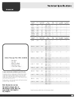
Cause: The generat or is no t powerful enough. See table.
Solution: R eplace the st eam generat or with one with a higher
heat output.
Cause: Ex cessiv e v entilation in the st eam r oom.
Solution: R educe the v entilation to evacuate 10–20 cubic
metres (1 3–26 cub. yd) of air per per son per hour .
Cause: Blo wn fuse in the main fuse bo x.
Solution: R eplace the fuse.
Cause: The ambient t emperature is lo wer than 15°C (59 °F).
Solution: Increase the ambient t emperature or replace the
steam generat or with a more po werful one.
Cause: Heating element is br oken.
Solution: R eplace element.
Cause: The thermostat sensor is t oo close t o the st eam jet.
Solution: Mo ve the sensor or change the direction of the
steam jet.
H
Ho
ott w
wa
atte
err rru
un
nss ffrro
om
m tth
he
e sstte
ea
am
m h
he
ea
ad
d.. L
Liittttlle
e
o
orr n
no
o sstte
ea
am
m iin
n tth
he
e sstte
ea
am
m rro
oo
om
m..
Cause: The solenoid v alve for incoming w ater has stuck,
due to accumulat ed deposits of f oreign bodies or an
electrical malfunction.
Solution: R emove the v alve and clean it, or rectify the
electrical malfunction.
Cause: The solenoid v alve is br oken.
Solution: R eplace the v alve.
Cause: Malfunction in the cir cuit boar d.
Solution: R eplace the cir cuit boar d.
E
Errrra
attiicc sstte
ea
am
m p
prro
od
du
uccttiio
on
n rriig
gh
htt ffrro
om
m tth
he
e sstta
arrtt..
Cause: The thermostat sensor is wr ongly placed in relation t o
the steam jet.
Solution: Mo ve the sensor or alt er the direction of the st eam
jet.
Cause: Calcium carbonat e or o ther foreign bodies in the f ilter.
Solution: R emove and clean the f ilter.
N
Ne
eiitth
he
err sstte
ea
am
m n
no
orr h
he
ea
att iiss g
ge
en
ne
erra
atte
ed
d iin
n tth
he
e
sstte
ea
am
m rro
oo
om
m..
Cause: Blo wn fuse in the mains fuse bo x.
Solution: R eplace the fuse.
Cause: The w ater is no t reaching the st eam generat or.
Solution: Open the tap(s) connect ed to the piping t o allo w
incoming w ater to flow into the st eam generat or.
Cause: The contr ol panel is incorrectly set.
Solution: Check the time and t emperature on the contr ol
panel.
Cause: The f ilter is clogged.
Solution: R emove the f ilter which is placed in the connection
for incoming w ater. Clean of f any metal f ilings or o ther foreign
bodies.
Cause: The solenoid v alve for w ater supply has stuck .
Solution: R emove the solenoid v alve and clean of f any metal
filings or o ther foreign bodies.
Cause: Ex cessiv e calcium carbonat e deposits in the st eam
generat or’s w ater reser voir.
Solution: R eplace the entire w ater reser voir, including heating
elements and electr odes.
Cause: The st eam generat or is wired up f or the wr ong v oltage.
Solution: Check the v oltage and the connection t o the
generat or – see diagram.
Cause: The t emperature limit contr ol has been triggered,
Solution: Check and remedy an y faults on the st eam pipe,
such as a block age due t o se veral sharp bends, w ater pock ets
or greatly reduced int ernal diamet er. The tank ma y also be
clogged with limescale.
Cause: Fla w in the cir cuit boar d, contr ol panel or magnetic
contactor.
Solution: R eplace the f aulty com ponent.
T
Te
em
mp
pe
erra
attu
urre
e ccu
utt-o
offff iiss a
accttiivva
atte
ed
d..
Cause: The st eam pipe is block ed.
Solution: R emove the block age.
Cause: The int ernal diamet er of the st eam pipe is
considerably reduced.
Solution: R eplace the pipe or the pipe joint which is causing
the reduction (Int ernal diamet er must be at least 12 mm, ½").
Cause: Sharp bends ( “elbows ”) along the st eam pipe.
Solution: Get rid of “elbows ” in the pipe. Bends are t o be
gently r ounded (minimum radius 50 mm, 2").
Cause: Large w ater pock et some where along the st eam pipe.
Solution: A djust the st eam pipe t o eliminate the w ater pock et.
Cause: Ex cessiv e calcium carbonat e deposits in the st eam
generat or’s reser voir.
Solution: R eplace the entire reser voir, including elements and
electrodes.
T
Th
he
e sstte
ea
am
m rro
oo
om
m m
ma
aiin
ntta
aiin
nss tth
he
e d
de
essiirre
ed
d tte
em
mp
pe
erra
attu
urre
e
((4
40
0–
–5
50
0°
°C
C,, 1
10
05
5–
–1
12
22
2°
°F
F)),, b
bu
utt n
no
o sstte
ea
am
m iiss p
prro
od
du
ucce
ed
d..
Cause: Insuf ficient v entilation in the st eam r oom.
Solution: Increase v entilation. The v entilation is insuf ficient if
less than 1 0–20 cubic metres (1 3–28 cub. yd) of air per
person per hour is e vacuated via the outlet v ent. This
situation ma y occur if the outlet v ent is no t connect ed to
some f orm of mechanical e xtractor fan – or if the v entilation
duct is block ed by a w ater pock et. (Commer cial applications)
Cause: The air coming int o the st eam r oom is t oo w arm.
Solution: R educe the intak e air temperature to 35°C (95 °F).
Cause: The ambient t emperature is higher than 35 °C (95 °F).
Solution: Ensure that the ambient t emperature does no t
exceed 35°C (95 °F).
Cause: The thermomet er is faulty or wr ongly placed.
Solution: The thermomet er should be placed appr oximately
(72") abo ve floor le vel and as f ar away from the st eam jet as
possible.
H
Ho
ott w
wa
atte
err cco
om
me
ess o
ou
utt o
off tth
he
e sstte
ea
am
m h
he
ea
ad
d iin
n
ssp
pu
urrttss o
orr iin
n a
a sslliig
gh
htt,, e
evve
en
n ffllo
ow
w m
miixxe
ed
d w
wiitth
h
sstte
ea
am
m..
Cause: Small w ater pock et along the st eam pipe.
Solution: Eliminat e the w ater pock et.
Cause: The st eam pipe is uninsulat ed along t oo great a
por tion of its length.
Solution: Insulat e the st eam pipe. A continuous trickle of ho t
water from the st eam generat or’s drainage pipe.
Cause: The solenoid v alve for automatic em ptying has stuck .
Solution: Switch of f the steam generat or. See what happens
again af ter an 80-minut e pause. If the f ault per sists, remo ve
the solenoid v alve for the aut omatic em ptying function and
clean it.
3 3
3
www.saunacore.com
Trouble Shooting
STEAMCORE
32
Summary of Contents for KWS 10.5
Page 25: ...s ight s Page 25...
Page 26: ...Page 26...


