


8
www.saunacore.com
S
TEAMCORE
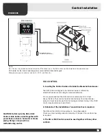
Steam Connections:
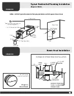
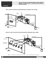
A ½ inch union fitting is supplied at the single steam outlet on KWS 2, KWS
3, KWS 4.5, KWS 7.5 model generators that will use one steam head. A 1
inch union fitting is supplied at the steam outlet on all KWS 9 to KWS 36
model generators. All 1 inch steam outlets on the unit must be reduced to
two ½ inch lines using a T reducer before reaching the steam room and the
½ inch pipe length to be close to equal lengths to the steam room. Each 1
inch steam line on your unit will require two standard steam heads or one
designer steam head. (Depending on the model, your steam generator may
have up to 4 - - 1 inch steam outlets on the unit that will be reduced to 8 ½
inch steam lines to the steam room, using 8 standard steam heads or 4
designer steam heads). Do not have any low points in the line that will allow
condensation to sit in the steam line(s). The steam heads should be
mounted approximatly 10 to 12 inches above the floor and 6” away from a
corner, located in an area where you will easily avoid physical contact.
Direct the steam head(s) outlet slot down and the fragrance reservoir up. If
steam room is provided or built with seat(s), locate steam head as far away
from seat as possible.
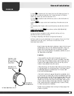
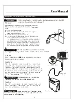
Drain:
This is a gravity draining system on all model steam bath generators. A ½
inch compression fitting is supplied with the unit and is to be installed on a
½ inch copper pipe that slopes slightly downwards and away from the unit.
It can be plumbed into an existing drain line or to an open floor drain. If
there is absolutely no drain available, you may direct it into the shower/
steam room. When connecting, you must use the two wrench method or
you may break the seal on the connection between the drain pipe and the
boiler tank, and cause leakage.
Testing: Now that your Steamcore is connected, you must test it.
1. Turn on your water supply and check for leaks.
2. Turn on your power supply at the electrical panel; be sure the unit is
receiving power.
3. Set the 30 minute mechanical timer to the desired time and wait for
steam.
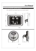
Option: Elegance Controls - - set temperature and press on
Option: Press Air Switch until red LED Light comes on and
wait (pre-programmed 30 minute timer and temperature set at 50
degrees Celsius)
4. Within a few minutes your steam room should begin to fill with steam.
5. Check to make sure your steam lines do not leak condensation and steam.
6. You may want to insulate the steam lines with pipe insulation; this is
strongly recommended if your steam generator is more than
1
0 feet from
the steam room.
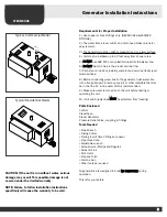
General Installation Instructions
(All Steam Bath Units)
NOTE:
To preserve steam head finish, do not use wrench
or other tools to tighten. Hand tightening is
sufficient when Teflon or equal pipe thread
sealing compound is used.
NOTE:
A drain valve is provided to facilitate servicing.
Where local codes permit, provide a drain line
connection from a generator drain valve. Check
local plumbing code for receptor, trap and vent
requirement. Unit drains by gravity. Slope down.
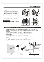
CAUTION !!
The steam head(s) (or nozzle(s)) create very
high degree of temperature in and around the
steam heads during use. The steam heads
should be installed as far away from any bathers
path. Bathers are to avoid this area and from any
direct contact to the steam heads. Burn or injury
may occur if touched or in the vicinity during use.
Appropriate protection should be provided to
avoid injury.
Summary of Contents for KWS 10.5
Page 25: ...s ight s Page 25...
Page 26: ...Page 26...


