Page 8
J2-
1
J2-
2
J1-
2
J1-
1
J1
J2
S
S
Supply
R
ed
B
la
ck
Red
Black
R
ed
R
ed
To Control Panal
F
il
l w
at
er
va
lve
D
ra
in
w
at
er
va
lve
Terminal Block
Yellow/Green
Red
Black
Red
B
lack
Y
e
ll
ow
Red
Black
R
ed
R
ed
R
ed
R
ed
Water Level Sensor
Red(Short Pin)
Black(Long Pin)
Yellow(Middle Pin)
R
ed
B
lack
Red
Blue
Brown
Red
Light
J1
-1
J1
-2
J1
S
S
L1
G
Supply
R
ed
Red
Black
To Control Panal
F
il
l w
at
er
va
lve
D
ra
in
w
at
er
v
al
ve
Terminal Block
Yellow/Green
Red
Black
Red
Bla
c
k
Y
e
ll
o
w
Red
Black
R
e
d
R
ed
R
e
d
R
ed
Water Level Sensor
Red(Short Pin)
Black(Long Pin)
Yellow(Middle Pin)
B
lack
Red
Blue
Brown
Red
Light
J1-
1
J1-
2
J1
S
S
Supply
R
ed
Red
Black
To Control Panal
F
il
l w
at
er va
lve
D
ra
in w
at
er
v
al
ve
Terminal Block
Yellow/Green
Red
Black
Red
Bla
c
k
Y
e
ll
o
w
Red
Black
R
ed
R
ed
R
e
d
R
ed
Water Level Sensor
Red(Short Pin)
Black(Long Pin)
Yellow(Middle Pin)
B
lack
Red
Blue
Brown
Red
Light
L2
B
lack
B
la
ck
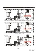
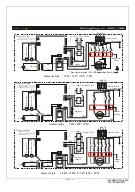
Wiring Diagram 240V(1PH)
N
L
L1
G
L2
N
L
L1
G
L2
N
L
Optional
Optional
Optional
Steamcore Spa * * 3kW (240V - 1PH)
Steamcore Spa * * 4.5kW (240V - 1PH)
Steamcore Spa * * 6kW / 7.5kW / 9kW (240V - 1PH)
Steamcore Spa * *
auto reset
hi-limit
auto reset
hi-limit
auto reset
hi-limit
manual
reset
hi-limit
manual
reset
hi-limit
manual
reset
hi-limit
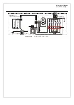
European Connection
( L2 = N "Neutral")
Summary of Contents for Xtreme Steam Tech Steamcore Spa II
Page 30: ... s ight s Page 28 ...
Page 31: ... ...


