background image


                        Ó

ÉÓ

ÚÕ

ôÆ

ûÅ

ç×

ìº

ÍÕ

ôÆ

û³

ö¿

Ú·

dz

£È

È£

¬Ó

¦

±

ÜÃ

â½

«

Õ

ô

Æ

ûÅ

ç×

ì°

²×

°Ô

ÚÁ

ÜÔ

¡Õ

ßÈ

ÝÒ

×¾

-

      ³

£½

Ó´

¥µ

½µ

ÄÎ

»Ö

ã

¬Ò

ÔÃ

âÅ

ç³

öµ

ÄÕ

ôÆ

û·

É

½

¦£

µ

¼Ö

Â

Ì

ÌÉ

ËÊ

¹Ó

ÃÕ

ßµ

ÄÎ

£Ï

Õ¡

£

×

¢

Ò

â


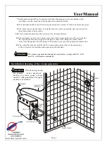
Water supply pipe  (1/2'')

!


  Ó

ÉÓ

Ú

Õ

ô

Æ

ûÅ

ç×

ìº

ÍÕ

ôÆ

û³

ö¿

Ú·

dz

£È

È£

¬Ó

¦±

ÜÃ

â½

«

Õ

ô

Æ

û

Å

ç×

ì°

²×

°Ô

ÚÁ

ÜÔ

¡Õ

ßÈ

ÝÒ

×¾

-


  ³

£

½

Ó´

¥µ

½µ

ÄÎ

»Ö

ã

¬Ò

ÔÃ

âÅ

ç³

öµ

ÄÕ

ôÆ

û·

ɽ

¦

£

µ

¼

Ö

Â

Ì

Ì

É

ËÊ

¹Ó

ÃÕ

ßµ

ÄÎ

£Ï

Õ¡

£

×

¢

Ò

â

!

Installation of pipeline


The installation of all the pipes should be

 done

 by

 a

 qualified 

licensed 

plumbe

r.


Warning:

1.

Use threaded unions when connecting pipes to fill/drain valves and steam line(s).

2.

Use brass or copper only.

3.

Do not use ABS, galvanized or PVC pipes. 

1.

Connect hot water or cold water. 

H

ot water with a temperature

 of not more


than 160

     .

2.

Install s

hutoff

 valve in the water supply pipe. The 

shut off

 valve should be installed in a  

place 

where it is easily operated in emergency.

3.

Clean the water supply pipe completely before connecting the water pipe to the steam 

generator.

4.

It is suggested that 

filter and anti-furring equipment 

be used 

in the water supply pipe.

5.

The water pressure should be  between 15 and 20 psi. If  necessary,


decrease the

 pressure accordingly.  Excess pressure may cause leakage.  The water flow rate should be aprox 8 gpm.

.

6.

If necessary, install equipment to prevent the water 

hammering

 sound, also install an approved

Steam Pipe

1.

Do not install any valves in the steam pipes. The steam can never be obstructed.

2.

Install one or more steam lines equal to your steam generator steam outlet(s) and with the same

 same diameter size copper steam pipe   between the steam outlet  and the steam nozzle.

3.

The heat insulation material used to insulate the steam pipe should be resistant to 

temperature as high as 250

 or higher.

4.

The horizontal part of the steam pipe should be installed inclining to the steam outlet or 

in the direction of steam 

generator

. Do not bend it in a 

s

hape to make the cooled 

water  stay in the curved pipe of the steam

 line

.

5.

The shorter the steam pipe, the better. Try to decrease the number of elbows and avoid 

abrupt turns.  Do Not combine steam lines if generator has more than one steam outlet.

 (Pipe Diameter: 3kW/4.5kW pipe size: 1/2'' 6kW &  above:  3/4'')

Attention:

                            Do not install the steam pipe in an upper or lower direction

 repeatedly

,

 this


 will affect the output of steam.

  Atte ntion:


Attention :


   Since the steam nozzle and steam outlet are very hot, try to avoid install

ing


the steam nozzle in the position which will easily come into contact with 

a

 person 


1.

Install the steam nozzle in the position 12 inches above the ground. If the steam bath is 

in the bathtub, install the steam nozzle 6 inches above the bathtub. If the 
steam room materials like acryl

ic

 or non-heat-resistant sheet, install 

additional heat insulator

s

.

2.

The steam outlet should be installed face down.

 Install the steam nozzle and tighten


with hands (use silicone).


   In order  to protect the steam nozzle, do not use 

wrench

 or other tools 

to tighten, use a little soap water and soft sponge to wipe, and do not use 

corrisve


chemical solutions or 

harsh

 cleaning tools.

Page 3

Steam nozzle

(3kW/4.5kW pipe  size: 1/2'' 6kW &  above: 3/4'')

User Manual

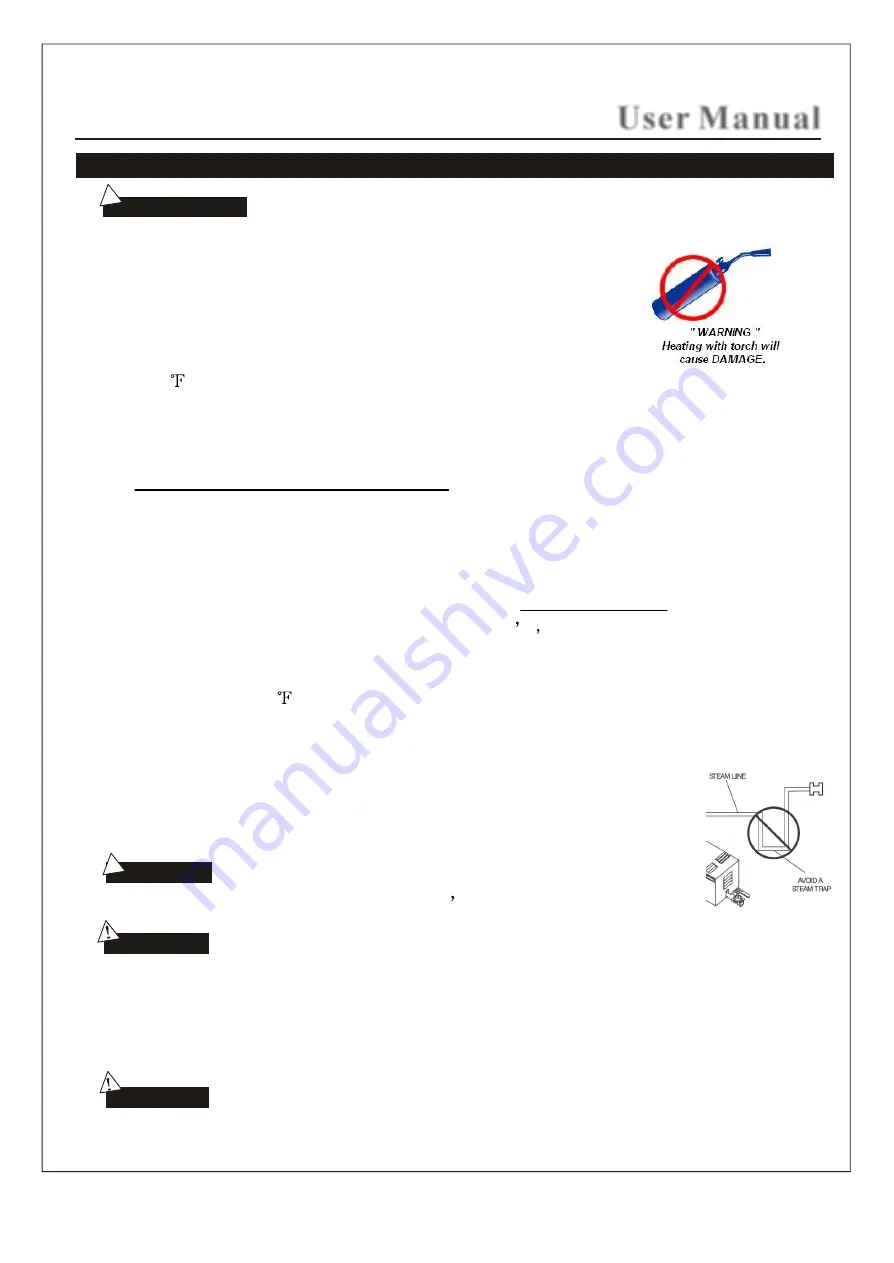
DO N OT  H EAT  AU T O FI LL / DRAI N  V ALV ES WI T H  T ORCH  DU RI N G I N ST ALLAT I ON .

This will cause damage to the plastic solenoid valve which will cause malfuction or leakage.

backflow preventer as required by local codes.  It is suggested that a thread on braided hose with a rubber

washer be used for the water supply line in order to attach the shutoff valve to the water intake solenoid. 

Also use adequate teflon tape around the thread of the solenoids for a tight seal between the two fittings.

Make sure for each steam outlet on the generator there is an individual

steam pipe to the steam room with the same diameter size as the outlet.

Install steam heads away from bathers path or from any direct contact.  Add appropriate protection 
to avoid bodily harm or burns.  

Summary of Contents for Xtreme Steam Tech Steamcore Spa II

Page 1: ...OPERATION INSTALLATION MANUAL STEAM GENERATOR STEAM GENERATOR aobsessed with qualiy aquality of life TM ...

Page 2: ...12 Steam generator structural drawing 13 Safety precautions of the controller 14 The safety and operating instruction of the controller 14 15 Controller installation instructions 16 17 18 18 20 20 Maintenance of the steam generator 22 Trouble shooting 23 Specifications 24 Control panel both SSI and SSII dimensions Temperature sensor installation only for SS I Control Panel Illustration for the con...

Page 3: ...tor should not be installed in the steamroom 3 Do not install outdoors or in any places that will influence the security of the machine by the environment 4 Do not install a frigid loft or any place water will freeze 5 Do not install it near burnable and combustible objects or chemicals 6 Install in a dry place and make adequate ventilation Page 1 Important Choosing a right location Install an exh...

Page 4: ...1 The steam pipe safety valve drain valve water tube steam outlet are still very hot after the steam generator has stopped working for some time Keep the steam outlet away from the people Bodily injury or burn may occur provide appropriate protection 12 The controller must be installed in the steam room please refer to the instruction of the controller s installation and operation of the manual Th...

Page 5: ...he cooled water stay in the curved pipe of the steam line 5 The shorter the steam pipe the better Try to decrease the number of elbows and avoid abrupt turns Do Not combine steam lines if generator has more than one steam outlet Pipe Diameter 3kW 4 5kW pipe size 1 2 6kW above 3 4 Attention Do not install the steam pipe in an upper or lower direction repeatedly this will affect the output of steam ...

Page 6: ...e Safety Valve Steam Pressure Valve has been supplied with this steam generator unit The steam generator has removable sealed plugs in place of the pressure valve mounting location labelled Unscrew the plugs and screw on the pressure relief safety valve supplied Make sure hi heat silicone is used to seal the safety valves to the boiler tank when attaching allow silicone to cure 24 hours The Pressu...

Page 7: ... hole Controller wire and light wire hole 304mm Safety valve Steam outlet Water inlet Water drainage 2 1 3 m m 1 9 0 m m 11 5 m m 29mm 156mm 260mm 3 0 7 m m 3 1 5 m m 3 3 5 m m 465mm 383mm Fuse for wire power supply Power wire hole Controller wire and light wire hole Fuse for wire power supply User Manual Fuse for wire power supply metal conduit connector required metal conduit connector required ...

Page 8: ...nce with national and local electricity consumption code and be installed by professional licensed electricians Attention to facilitate maintenance keep the steam engine clean If the information provided is limited do not touch the pipeline and electric equipment Attention Caution to avoid damage to the equipment do not connect strong electric current directly to the components 510mm 435mm Steam o...

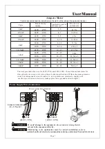
Page 9: ...tion refer to national and local electricity consumption codes by professional licensed electricians Attention Warning Page 7 240V 1PH 240V 1PH 240V 1PH 240V 1PH 240V 1PH 208V 3PH 240V 1PH 240V 1PH 208V 3PH 12 5A 18 75A 25A x 3 Type Applicable space of 3 the room m E l e c t r i c i t y supply E l e c t r i c current A L1 L2 L3 240V 1PH 208V 3PH L1 L1 L2 L3 Power connection terminal User Manual 3k...

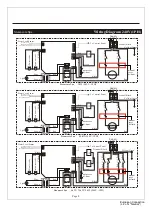
Page 10: ...ed Short Pin Black Long Pin Yellow Middle Pin Black Red Blue Brown Red Light J1 1 J1 2 J1 S S Supply Red Red Black To Control Panal Fill water valve Drain water valve Terminal Block Yellow Green Red Black Red Black Yellow Red Black Red Red Red Red Water Level Sensor Red Short Pin Black Long Pin Yellow Middle Pin Black Red Blue Brown Red Light L2 Black Black Wiring Diagram 240V 1PH N L L1 G L2 N L ...

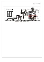
Page 11: ...ed Black Red Black Yellow Red Black Red Red Red Red Water Level Sensor Red Short Pin Black Long Pin Yellow Middle Pin Red Black Red Blue Brown Red Light Red Red Supply J2 J3 J2 1 Black J3 1 Black Black Black L1 G L2 N L Optional Steamcore Spa 10 5kW 18kW 240V 1PH auto reset hi limit manual reset hi limit European Connection L2 N Neutral ...

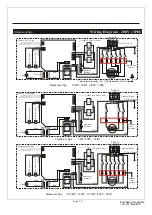
Page 12: ...ong Pin Yellow Middle Pin Red Red Blue Brown Red Light G L1 L2 L3 Red Red J1 2 Red Red J1 1 Red Red J3 2 Red Red J2 To Control Panal Terminal Block J2 2 J1 1 J1 2 J3 1 J2 1 J3 2 J1 J2 J3 Yellow Green Red Black Black Red Black G Supply L1 L2 L3 Red S S Fill water valve Drain water valve Yellow Red Black Red Red Red Red Water Level Sensor Red Short Pin Black Long Pin Yellow Middle Pin Red Blue Brown...

Page 13: ...t feet of the current steam shower or bathtub area Example L 7xW 5xH 8 280 Cubic Feet You would need a 9000 watt 9KW steam generator However if your shower materials are x 25 for Ceramic Wall Finish 61 25 61 25 280 341 Total that has a ceramic wall finish is multiplied by Acrylic cultured marble Ceramic Tile on Cement Board Ceramic Tile on Mortar Bed Glass or Glass Block Porcelain tile on cement b...

Page 14: ...isture proof measures in the process of installation Do not let the electrical components be exposed to moisture or it will cause damage or short circuit The illustration is just for explaination the practical installation must comply with the nation s electric criteria and performed by a professional licensed electrician CAUTION Possible location The steam outlet Under Sink possible location The ...

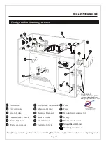
Page 15: ...use Ground wire connector 16 Relay Water level sensor 17 15 14 13 Page 13 Configuration of steam generator Fuse 13 17 9 User Manual Use teflon tape and rubber gasket washer when attaching fittings to the water fill and drain valve to create a liquid tight seal Pressure Safety Valve DO NOT HEAT DURING INSTALLATION heating with torch will cause damage to plastic solenoid valve Mood light transformer...

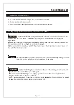
Page 16: ...e steam room will be too high or not heated enough If the controller is installed outside the steam room the temperature sensor must be installed in the steam room Caution Do not install the controller wire in the same conduit with high voltage electric wire Do not install close to hot water or steam pipe Important Before installing the controller make sure the steam generator power is off otherwi...

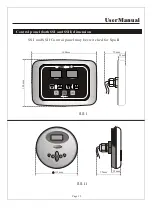
Page 17: ...Page 15 User Manual Control panel both SSI and SSII dimension 113mm 25mm 75mm SSI and SSII Control panel may be switched for Spa II SS I SS I I 160mm 120mm 23mm 70mm ...

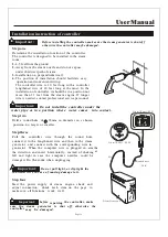
Page 18: ...nual Important Do not install the controller under the water pipe or in a position where water comes into contact Step two Drill a round hole of 35mm in diameter in a chosen position no larger or smaller Step three Pull the controller wire through the round hole connect it to the lengthened wire and then to the steam generator and connect with the corresponding wire in the generator When the compu...

Page 19: ...n Fig 2 5 Let the temperature sensor go through the back of the sensor holder As shown in Fig 3 6 The temperature sensor should be installed by extending about 1cm from the front of the room to make sure the speed and accuracy of temperature control 7 Apply silicone to the back and fix the sensor As shown in Fig 3 Fig 1 Fig 2 Fig 3 Temperature sensor base optional Step five Remove the paper on the...

Page 20: ...ON OFF When unit is powered on power indicator LED should be lit Press and release button to activate system and all function buttons Meanwhile power indicator LED goes out Water input steam boil tank automatically and LED screens display Shut down the system press button again System drains out water in generator water tank automatically NOTE If power indicator LED flashes when system is activate...

Page 21: ...s activated Steam time LED screen shows set time from 5 60 minutes System shuts down power supply to heater elements automatically when desired steam time is over Use and buttons to set desired steam temperature when system is activated Steam temperature LED screen shows set steam temperature ranging from When ambient temperature is higher than desired temperature system shuts down powersupply to ...

Page 22: ...ime to keep the temperature in the set number ON OFF When it is electrified the system shuts off all the loads to remain in a waiting state and the digital tube will display as is shown in Fig 1 In the waiting state press button to turn on the system and the steam function The default time of starting the steam is 30 minutes and it begins to count down and the default temperature of the steam is 1...

Page 23: ...nment temperature When the system is started press button or when the steam function time is due the system will be shut 10 minutes after the system is shut off the drainage function will be started automatically for 5 minutes Time setting When the machine is started press button and the digital tube will display the remaining time of current steam function as shown in Fig 4 press button or button...

Page 24: ... is shown in Fig 7 1 Wait for the completion of automatic water discharge after each time of using the steam generator to make sure the water in the tank is discharged completely before cutting off power supply 2 There should not be any leakage or damage among the steam generator steam nozzle components and pipes They should be checked and repaired annually 3 Clean the water supply pipes of the st...

Page 25: ...re steam unit with the advanced IntelliSteam controller This booklet will help you get the most enjoyment out of your device s many capabilities and features S t e a mc o r eI n t e l l i S t e a mO p e r a t i n gI n s t r u c t i o n s ...

Page 26: ...e touched for 20 seconds the system will auto lock the keypad and the Dotted line Solid line indicator on the display screen will flash Touching the Power Key for 3 seconds will unlock the system making all keys active 3 Using the Steam Function With the system on touch the Steam key to initiate steam generation The radio must be off to initiate the steam function An indicator will show this opera...

Page 27: ...e tuner A third touch shuts the CD function off completely If no CD is installed touching the Radio key a second time will simply turn off the radio function 9 Radio Tuning Search Power on radio function selected 1 Auto search store Touch the TUN key for 2 seconds or more to turn on auto search store The tuner range is from 97 5 108 0MHZ reception location dependant This will store the strongest a...

Page 28: ...nnecting touch the Bluetooth Now you can use Bluetooth to play music or answer a call Touching the Up key skips to the next song and touching the Down key skips back to the previous one Touch TUN TEL to pause playing and again to resume play When you receive an incoming phone call touch TUN TEL to answer and again to hang up Touching the Bluetooth key again will turn off the Bluetooth function 4 E...

Page 29: ...This set of instruction pages is to be used in combination with the Steamcore Steam Bath installation manual provided with each steam bath generator ...

Page 30: ... s ight s Page 28 ...

Page 31: ... ...

Page 32: ...een the control panel and the electrically controlled box has become loose and whether the power circuitry has good contact 2 Change a plugboard Water leakage 1 The water pipe connector becomes loose or the pipe breaks 2 Water leakage in the water input valve or the waterdrainage valve 1 Tighten the loose connector and change the broken pipe 2 Change the water input valve or the water drainage val...

Page 33: ...User Manual Min 208V 3PH 240V 1PH 208V 3PH 240V 1PH 12 5A 18 75A 25A x 3 31 25A 37 5A 43 75A 33 3A x 337 5A x 341 7A x 3 50A x 3 25A 50A 12V 40W 12V 40W12V 40W12V 40W 12V 40W 12V 40W 12V 40W 12V 40W 12V 40W 12V 40W 0 12MPa 0 12MPa 0 13MPa 0 14MPa 0 14MPa 0 15MPa 0 16MPa 0 17MPa 0 18MPa 0 19MPa 500ml Min 450ml Min 400ml Min 360ml Min 300ml Min 260ml Min 220ml Min 180ml Min 160ml Min 140ml Min 100 1...

Page 34: ...___________________________________ Dealer Name and Adress ____________________________________________________________________________________________ Owner Name and Address ____________________________________________________________________________________________ NOTE A COPY OF THE RECEIPT MUST ACCOMPANY THIS WARRANTY CARD Warranty applies only to the original consumer purchaser warranty is no...

Reviews: