22
2000225294A
Diagram 7.1
7 Installation Preparation and Appliance Fixing
7.1 Unpacking of Boiler
IMPORTANT:
With regards to the Manual Handling Operations,
1992 Regulations, the following lift operation exceeds the
recommended weight for a one man lift.
Stand the boiler carton upright.
Cut and remove the securing straps and lift off the carton
sleeve. Place aside any loose components until required.
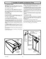
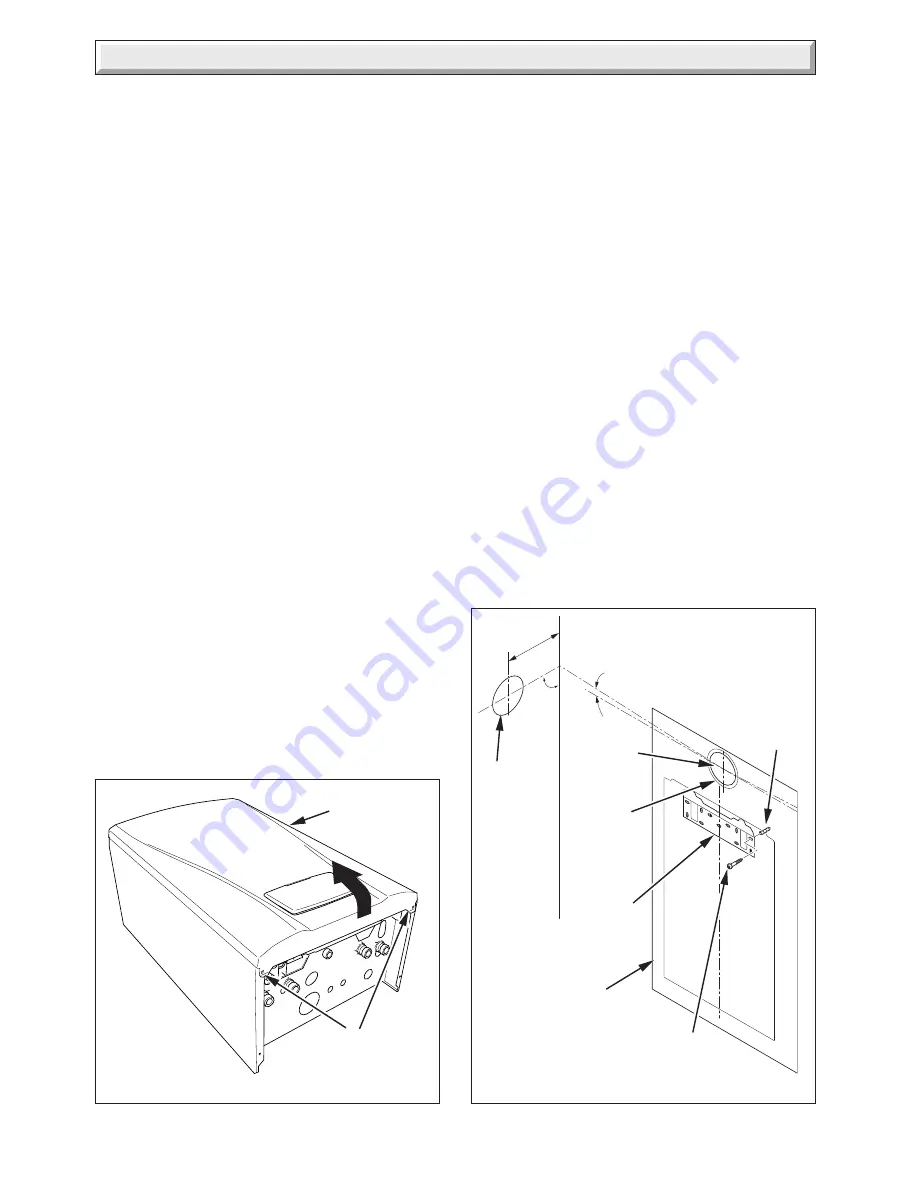
Carefully lay the boiler on its back, remove the two front casing
panel securing screws and lift off the panel from two retaining
lugs,
see diagram 7.1
.
7.2 Wall Template
Remove the wall template from the installation pack and place
in the desired position on a flat wall, giving due consideration to
boiler clearances,
see section 6
.
7.3 Horizontal Flue Hole Cutting
Mark the centre of the flue hole and remove the wall template.
The
standard horizontal flue
is designed with an internal fall
of 35mm/metre towards the boiler for disposal of condensate.
If the standard flue length alone is being used then the flue hole
of diameter 105mm can be cut in the position marked on the wall
template.
For
standard side flues
the horizontal flue centre line on the
wall template should be extended to the side wall, and the
vertical centre of the flue hole marked at 206mm from the back
wall.
For installations with external access, a 105mm diameter core
drill can be used.
For installations with internal access only a 125mm diameter
core drill should be used.
Diagram 7.2
When using extension pipes with the horizontal rear flue, a core
drill size of 125mm should be used to allow the extension pieces
to slope at 35mm/metre (2.5
o
) towards the boiler.
For
extended side flues
, the flue hole centre should be
determined by extending the dashed inclined line on the template
to the side wall. This dashed line is drawn at 35mm/metre (2.5
o
)
rise from the boiler. Where this line reaches the side wall, a
horizontal line should be marked. The vertical centre line of the
flue should then be marked at 206mm from the back wall,
see
diagram 7.2.
To allow for the flue passing through the wall at this angle a
125mm hole should be drilled irrespective of internal or external
installation.
7.4 Appliance Fixing
Reposition the wall template mark the position of the hanging
bracket fixing holes. Drill the fixing holes and insert suitable wall
plugs. Fix the hanging bracket to the wall using suitable screws,
see diagram 7.2.
Lift the boiler into position in the following manner.
Lean the top of the boiler slightly to the wall and position just
above the hanging bracket. Allow the boiler to slowly move
downwards until engaged in the hanging bracket.
FRONT
CASING
PANEL
SECURING
SCREWS
HANGING
BRACKET
WALL
TEMPLATE
SCREW
WALL
PLUG
206mm
ø105
Standard
Horizontal -
Standard flue
2.5
°
Inclined -
Extended flue length
90
°
11902
ø105
EXTERNAL
FITTING
ø125
INTERNAL
FITTING
12182
ø125
Extended
Summary of Contents for EnviroPlus F24e
Page 18: ...18 2000225294A Diagram 5 1 11907 5 Boiler Schematic F24e F28e ONLY ...
Page 19: ...19 2000225294A 5 Boiler Schematic Diagram 5 1a 12248 BYPASS F28e SB ONLY ...
Page 49: ...49 2000225294A 14 Fault Finding 12410 Diagram 14 4 ...
Page 51: ...51 2000225294A 15 Wiring Diagram Diagram 15 1a 12240 F28e SB ONLY ...


