24
2000225294A
BOILER
BOILER
8 Horizontal Top Flue Preparation and Fitting
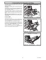
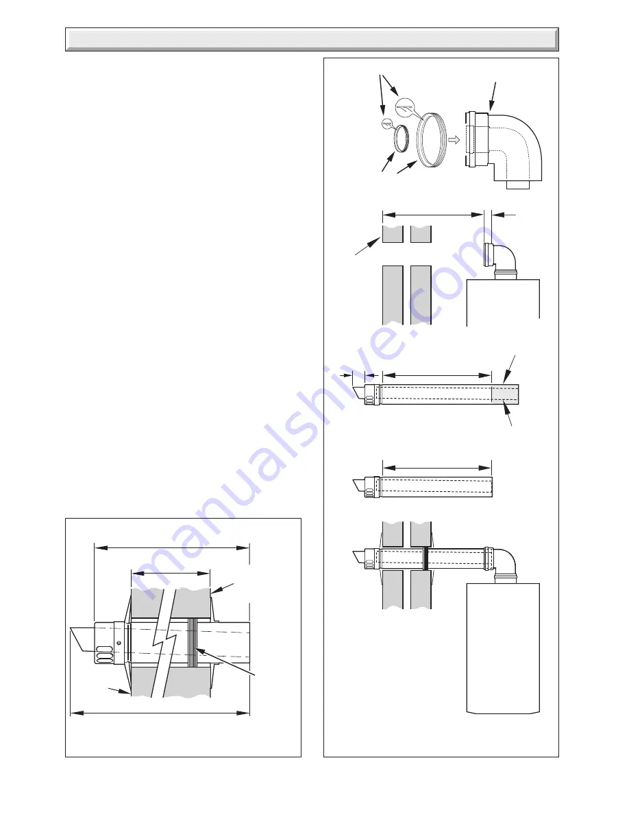
Diagram 8.4
X + 240
( AIR DUCT ASSEMBLY)
X + 305
( FLUE DUCT )
X
OUTSIDE
WALL
FACE
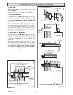
Diagram 8.5
SIDE DUCT - STANDARD / EXTENDED FLUE
12257
BOILER
MOUNTING
WALL
11904
REAR FLUE
OUTSIDE
WALL
FACE
AIR DUCT
FLUE
DUCT
SPACER
PIECE
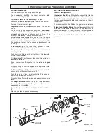
8.2 Rear Flue
Mark the air duct assembly and the flue duct at the lengths
shown in
diagram 8.4.
Then cut to length, cutting square and removing any burrs.
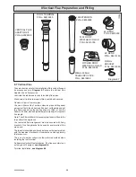
8.3 Standard Side Flue
Fit the flue spigot 'H', supplied with the boiler with the three
securing screws to the top of the boiler. Fit the flue elbow 'G' to
the flue spigot a small amount of lubricant should be applied to
the seal before fitting the flue elbow,
see the relevant part of
diagram 8.6.
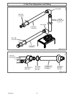
Measure from the outside wall face to the flue elbow 'Y' add
45mm. Measure and mark the flue to length. Make sure that the
flue duct groove is engaged on air duct tab and is pushed fully
into the air duct. When fully engaged the measurment at the end
of the terminal will be 65mm. Then cut, cutting square and
removing any burrs,
see diagram 8.5.
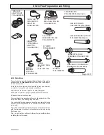
8.4 Side Flue With Extensions
Fit the flue spigot 'H', supplied with the boiler with the three
securing screws to the top of the boiler. Fit the flue elbow 'G' to
the flue spigot a small amount of lubricant should be applied to
the seal before fitting the flue elbow,
see the relevant part of
diagram 8.6.
Measure from the outside wall face to the flue elbow 'Y' add
45mm. Measure and mark the flue to length. Make sure that the
flue duct groove is engaged on air duct tab and is pushed fully
into the air duct. When fully engaged the measurment at the end
of the terminal will be 65mm. Then cut, cutting square and
removing any burrs,
see diagram 8.5.
45
'Y'
'Y'+45
CUT
AIR DUCT AND
FLUE DUCT CUT
TO LENGTH
FLUE ASSEMBLY
FITTED TO BOILER
(LIPS POINT INWARDS)
FLUE ELBOW
LIP SEALS
65
Summary of Contents for EnviroPlus F24e
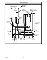
Page 18: ...18 2000225294A Diagram 5 1 11907 5 Boiler Schematic F24e F28e ONLY ...
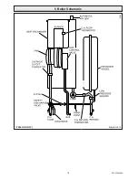
Page 19: ...19 2000225294A 5 Boiler Schematic Diagram 5 1a 12248 BYPASS F28e SB ONLY ...
Page 49: ...49 2000225294A 14 Fault Finding 12410 Diagram 14 4 ...
Page 51: ...51 2000225294A 15 Wiring Diagram Diagram 15 1a 12240 F28e SB ONLY ...


