28
2000225294A
8 Twin Flue Preparation and Fitting
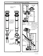
8.10 Twin Flue
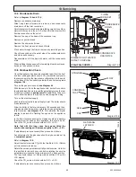
These instructions are for the installation of this twin flue and its
accessories only.
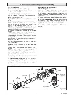
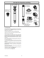
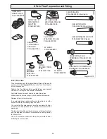
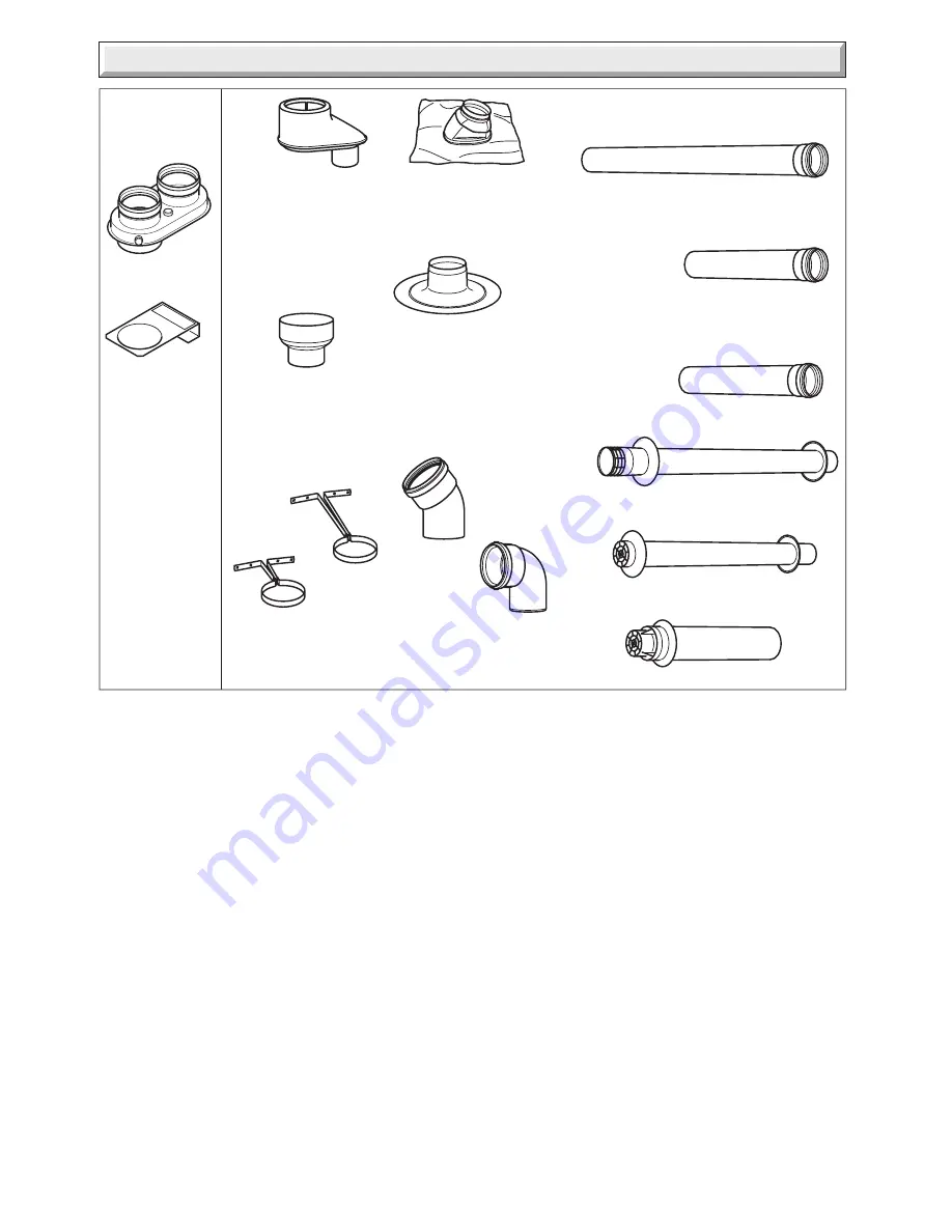
Diagram 8.10
shows the Twin Flue Adaptor
kit and Accessories.
Refer to the Flue Options Guide available from your nearest
stockist for flue lengths and sample installations.
Lubricate the rubber seals prior to inserting flue pipes.
Make sure all joints are properly fitted, sealed and secured.
Remove all burrs from cut pipes.
If an extension pipe requires cutting, cut the plain end not the
flared end where the sealing rings are fitted.
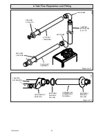
Your selected flue arrangement must be secured with fixing
brackets. One fixing bracket to be used for every metre of flue
pipe used.
The terminal should be positioned as to cause the least problem
with the dispersal of products of combustion and any pluming
that may occur.
The use of weather collars are the preferred method when
installing the roof terminal.
Diagram 8.10
12209
TWIN FLUE
ADAPTOR KIT
Pt.No.A2025000
TWIN PIPE TO
CONCENTRIC
ADAPTOR
Pt.No.08511800
SINGLE PIPE
TO TERMINAL
ADAPTOR
Pt.No.08511900
FLAT ROOF
WEATHER COLLAR
Pt.No.08510700
PITCHED ROOF
WEATHER COLLAR
Pt.No.08510500
45
°
BEND
Pt.No.08538800
90
°
BEND
Pt.No.08538700
FIXING
BRACKET TWIN
FLUE
Pt.No.08511700
FIXING
BRACKET
VERTICAL
Pt.No.08512000
1M EXTENSION
Pt.No.08547800 (Aluminium)
HORIZONTAL FLUE
TERMINALS Pt.No.08511500
CONCENTRIC HORIZONTAL
TERMINAL Pt.No.08584900
0.5M EXTENSION AIR DUCT
Pt.No.08547200 (Plastic)
0.5M EXTENSION
Pt.No.08547600 (Aluminium)
Summary of Contents for EnviroPlus F24e
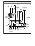
Page 18: ...18 2000225294A Diagram 5 1 11907 5 Boiler Schematic F24e F28e ONLY ...
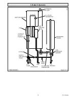
Page 19: ...19 2000225294A 5 Boiler Schematic Diagram 5 1a 12248 BYPASS F28e SB ONLY ...
Page 49: ...49 2000225294A 14 Fault Finding 12410 Diagram 14 4 ...
Page 51: ...51 2000225294A 15 Wiring Diagram Diagram 15 1a 12240 F28e SB ONLY ...


