32
2000225294A
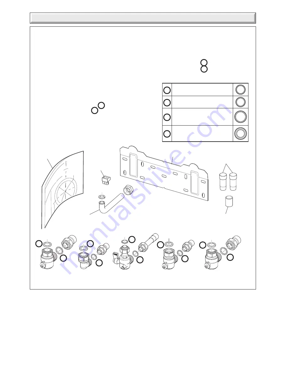
15mm
15mm
15mm
15mm
b 1/2 in. gasket
a Ø15mm sealing washer
c 3/4 in. gasket
d Polyacetal gasket
22mm
22mm
HANGING BRACKET
WALL
TEMPLATE
CENTRAL
HEATING
FLOW
DOMESTIC
HOT WATER
OUT
GAS
ISOLATING
VALVE
SAFETY
DISCHARGE
PIPE
DOMESTIC
COLD WATER
SUPPLY IN
CENTRAL
HEATING
RETURN
FILLING
DEVICE
EXTENSIONS
3 POLE
INLINE
PLUG
CONDENSE
ADAPTER
c
c
d
d
d
d
a
b
b
b
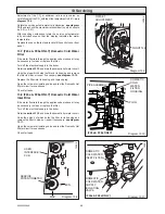
9 Gas/Water Connections
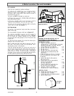
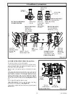
9.1 Gas Connection
The position is shown on the wall template.
A gas pipe, gas isolating valve and gaskets are supplied in
packs at the bottom of the boiler packaging.
Refer also to
section 1.
Remove plug from gas isolating valve.
Fit the sealing washer into the securing nut attached to the gas
isolating valve. Connect the gas isolating valve to the boiler. Fit
the sealing washer into the securing nut attached to the gas pipe
Diagram 9.1
12261
and make good the final connection to the gas isolating valve,
see diagrams 9.1 and 9.2
.
Do not subject the gas isolating valve to heat.
The whole of the gas installation, including the meter, should be
inspected, tested for soundness and purged in accordance with
the current issue of BS6891 and in IE the current edition of
I.S.813 " Domestic Gas Installations ".
Refer also to
Section 1.
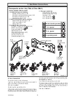
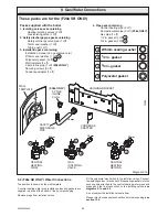
These packs are for the (F24e & F28e ONLY)
Packs supplied with the boiler
1. Isolating valve pack containing
Heating isolating valves (2 off)
Domestic cold water isolating valves (1 off)
Domestic hot water elbow (1 off)
Gas isolating valve (1 off)
2. Safety discharge pipe pack containing
Safety discharge valve pipe (1 off)
15mm seal washer (1 off)
Tubing nut (1 off)
3. Installation pack containing
Installation manual (inc. guarantee card)
Ø15mm seal washer (1 off)
a
Polyacetal gasket (4 off)
d
Wall template (1 off)
Filling device extensions (2 off)
3 pole inline plug (1 off)
Securing screws (3 off)
Condense adapter (1 off)
4. Pipe pack containing
Central heating pipe (2 off)
Domestic water pipe (2 off)
Gas pipe (1 off)
1/2 in. gasket (3 off)
b
3/4 in. gasket (2 off)
c
Summary of Contents for EnviroPlus F24e
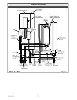
Page 18: ...18 2000225294A Diagram 5 1 11907 5 Boiler Schematic F24e F28e ONLY ...
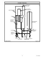
Page 19: ...19 2000225294A 5 Boiler Schematic Diagram 5 1a 12248 BYPASS F28e SB ONLY ...
Page 49: ...49 2000225294A 14 Fault Finding 12410 Diagram 14 4 ...
Page 51: ...51 2000225294A 15 Wiring Diagram Diagram 15 1a 12240 F28e SB ONLY ...

