38
2000225294A
11 Electrical Connections
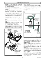
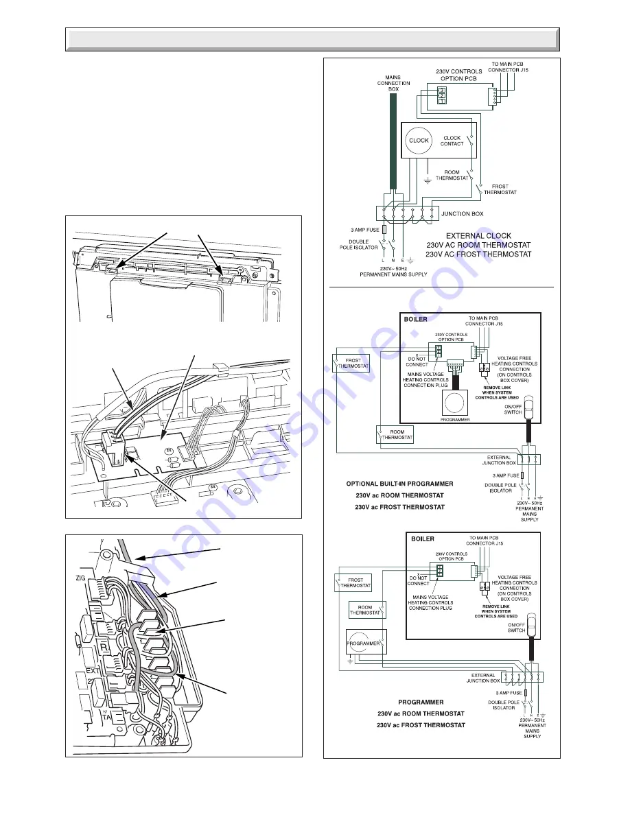
STRAIN
RELIEF
MAINS
CABLE
SYSTEM
CONTROLS CABLE
( MAINS VOLTAGE)
RETAINING LATCHES
Diagram 11.4
CABLE
EXIT
11974
Diagram 11.5
11984
SYSTEM
CONTROLS
CABLE
11983
CONTROLS
OPTION PCB
PLUG
Diagram 11.3
11987
12184
CONTROLS PANEL
USER INTERFACE
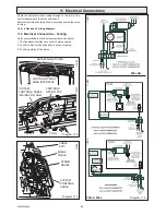
Route the external controls cable through to the rear of the
control panel where the other cables exit.
External controls should be fitted in accordance with the rules
in force.
Refer to
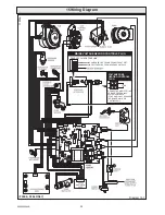
Section 15 wiring diagram.
11.3 Electrical Connections - Testing
Carry out preliminary electrical system checks as below:
1. Test insulation resistance to earth of mains cables.
2. Test the earth continuity and short circuit of cables.
3. Test the polarity of the mains.
11627
F28e SB
F24e & F28e
Summary of Contents for EnviroPlus F24e
Page 18: ...18 2000225294A Diagram 5 1 11907 5 Boiler Schematic F24e F28e ONLY ...
Page 19: ...19 2000225294A 5 Boiler Schematic Diagram 5 1a 12248 BYPASS F28e SB ONLY ...
Page 49: ...49 2000225294A 14 Fault Finding 12410 Diagram 14 4 ...
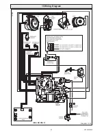
Page 51: ...51 2000225294A 15 Wiring Diagram Diagram 15 1a 12240 F28e SB ONLY ...

