41
2000225294A
13 Servicing
13.1 General
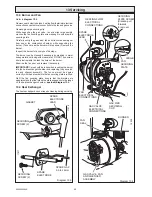
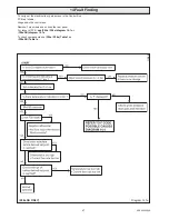
Measurement of the products of combustion can be achieved
by connection of a probe to the flue elbow or alternatively to the
sample point at the base of the flue outlet pipe inside the boiler
,
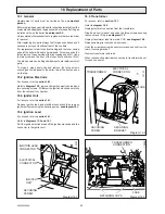
see diagram 13.2.
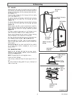
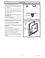
To gain access remove the front casing and inner casing
panels,
see diagram 13.1.
To remove the front casing panel remove the two securing
screws and lift off the panel from two retaining lugs,
see
diagram 13.1.
To remove the inner casing panel remove the two securing
screws and lift off the panel from two retaining lugs,
see
diagram 13.1.
Before commencing with a service or replacement of parts the
boiler should be isolated from the electrical supply and the gas
supply should be turned off at the gas isolation valve,
see
diagram 9.2.
All routine servicing requirements can be achieved by the
removal of the front casing and inner casing panels only.
Unless stated otherwise any part removed during servicing
should be replaced in the reverse order to removal.
Servicing should always include the removal of any debris from
the condensate pipe and siphon,
refer to Section 13.5.
After completing any servicing of gas carrying components,
ALWAYS test for gas soundness and carry out a functional test
of the controls.
Testing Flue Gases:
If any doubt exists that the flue products
are not exhausting correctly, investigate by use of a gas
analyser (FGA).
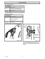
13.2 Spark Electrode
Disconnect the electrode lead and two securing screws.
Withdraw the spark electrode carefully from the combustion
chamber,
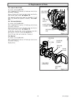
see diagram 13.3.
NOTE:
On reassembly do not overtighten screws.
Inspect the tips for damage.
Clean away any debris and check the spark gap is 3.5 to 4.5
mm.
Check the electrode sealing gasket for signs of damage and
replace if necessary.
Diagram 13.2
FLUE
OUTLET
PIPE
COMBUSTION
SAMPLE
POINT
FLUE
ELBOW
COMBUSTION
SAMPLE
POINT
Diagram 13.1
RETAINING
LUGS
FRONT CASING
PANEL
SECURING
SCREWS
INNER CASING
PANEL
RETAINING
LUGS
SECURING
SCREWS
Summary of Contents for EnviroPlus F24e
Page 18: ...18 2000225294A Diagram 5 1 11907 5 Boiler Schematic F24e F28e ONLY ...
Page 19: ...19 2000225294A 5 Boiler Schematic Diagram 5 1a 12248 BYPASS F28e SB ONLY ...
Page 49: ...49 2000225294A 14 Fault Finding 12410 Diagram 14 4 ...
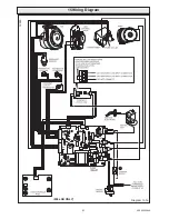
Page 51: ...51 2000225294A 15 Wiring Diagram Diagram 15 1a 12240 F28e SB ONLY ...


