44
2000225294A
13 Servicing
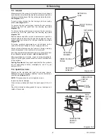
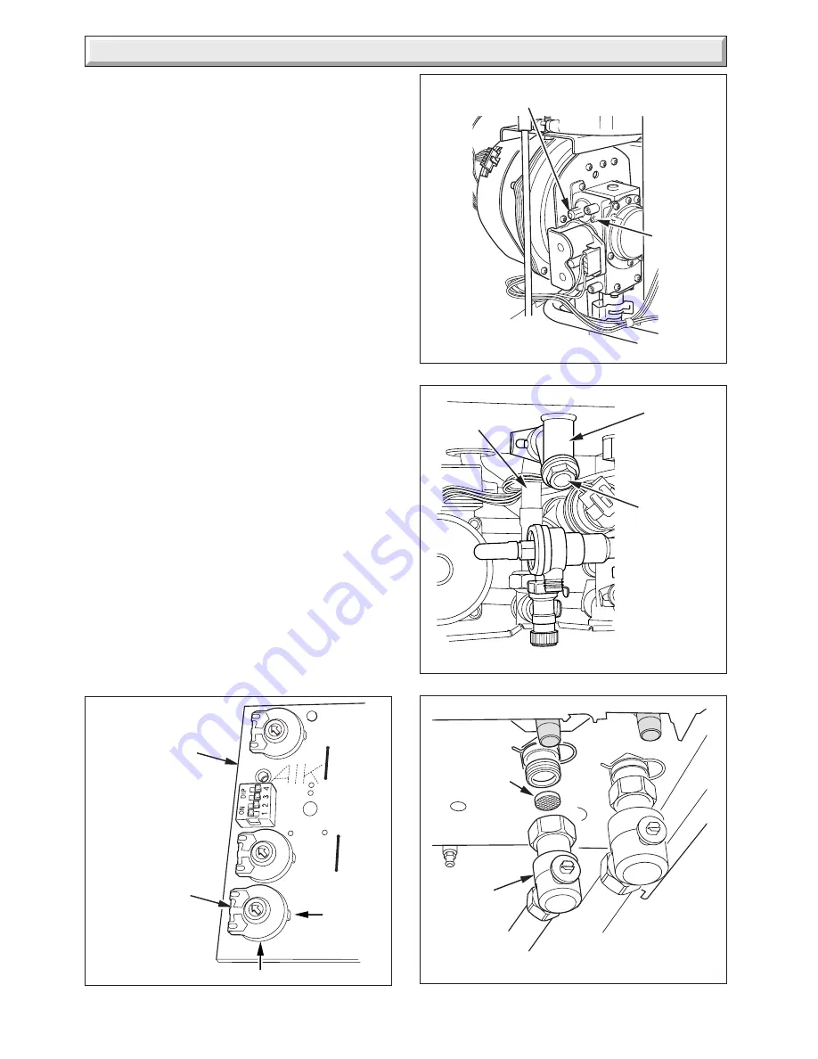
Diagram 13.11
12262
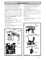
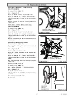
Adjustment of the CO
2
at minimum rate is very coarse so
carefully adjust the CO
2
with the offset adjustment to 8.3%,
see
diagram 13.9
.
Rotate the service potentiometer fully clockwise,
see diagram
13.8
and recheck the maximum rate combustion, which should
be 9.3%
±
0.2%.
After checking combustion rotate the service potentiometer
fully anti-clockwise so that the display indicates the water
temperature.
Replace the cap on the test point and refit the control cover front
panel.
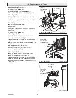
13.7 (F24e & F28e ONLY) Domestic Cold Water
Filter
If the water flow rate through the appliance has reduced it may
be necessary to clean or replace the filter.
Turn off the electrical supply to the boiler.
Refer to
section 13.10
and drain the domestic hot water circuit.
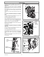
Undo the plug which holds the filter in its housing and remove
the filter to clean or renew if necessary,
see diagram 13.10.
Replace the filter into its housing and replace plug.
Open the cold water isolating valve and test the Domestic Hot
Water circuit for soundness.
Check for leaks.
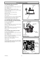
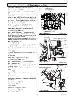
13.8 (F24e & F28e ONLY) Domestic Cold Water
Inlet Filter
If the water flow rate through the appliance has reduced it may
be necessary to clean or replace the filter.
Turn off the electrical supply to the boiler.
Refer to
section 13.10
and drain the domestic hot water circuit.
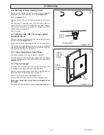
Undo the union nut which holds the filter in its housing and
remove the filter to clean or renew if necessary,
see diagram
13.11.
Open the cold water isolating valve and test the Domestic Hot
Water circuit for soundness.
Check for leaks.
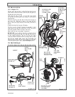
Diagram 13.8
THROTTLE
OFFSET
ADJUSTMENT
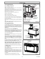
Diagram 13.9
MIN.
SERVICE
POTENTIOMETER
MAX.
12265
USER
INTERFACE
PCB
12256
Diagram 13.10
PLUG
DOMESTIC
COLD
WATER
FILTER
HOUSING
12193
PIPE ASSEMBLY
DOMESTIC
COLD WATER
SUPPLY
ISOLATING
VALVE
(F24e & F28e ONLY)
(F24e & F28e ONLY)
DOMESTIC
COLD WATER
INLET FILTER
Summary of Contents for EnviroPlus F24e
Page 18: ...18 2000225294A Diagram 5 1 11907 5 Boiler Schematic F24e F28e ONLY ...
Page 19: ...19 2000225294A 5 Boiler Schematic Diagram 5 1a 12248 BYPASS F28e SB ONLY ...
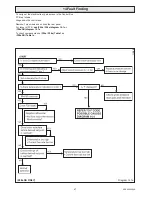
Page 49: ...49 2000225294A 14 Fault Finding 12410 Diagram 14 4 ...
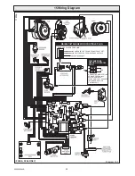
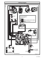
Page 51: ...51 2000225294A 15 Wiring Diagram Diagram 15 1a 12240 F28e SB ONLY ...

