Installation and servicing instructions strictly reserved for qualifi
ed gas installers
13
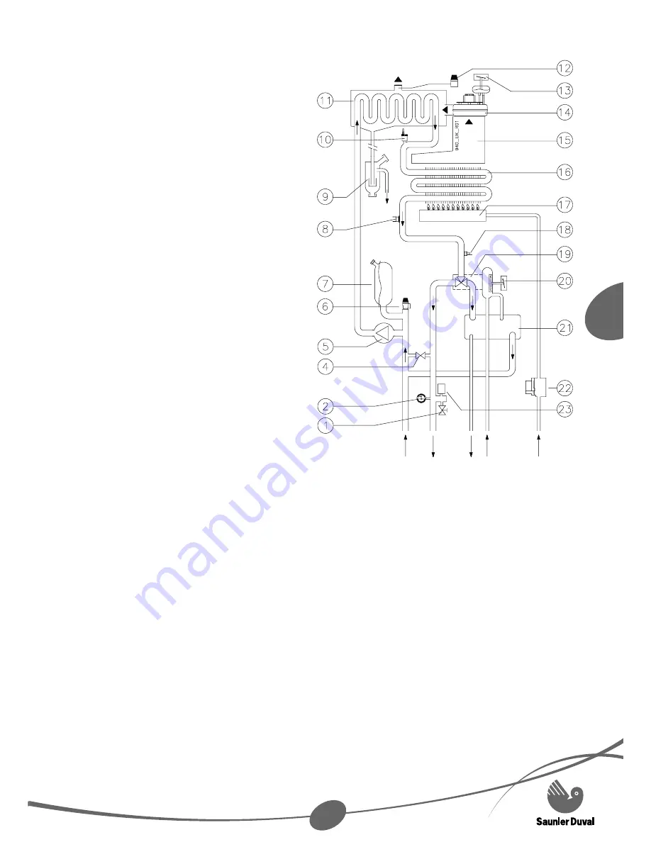
2.3 Block
diagram
HEATING
DOMESTIC
WATER
GAS
(white)
1 Drain
valve
2
Pressure gauge / thermometer
4 By-pass
5 Pump
6
Heating system safety valve 3 bar
7 Expansion
vessel
8 Overheat
thermostat
9 Condense
syphonic
trap
10 Automatic air vent
11 Recuperator
12 Flue overheat safety thermostat
13 Air pressure switch
14 Fan
15 Flue
hood
16 Primary
heat
exchanger
17 Burner
18 Thermistor
19 Hydraulic 3-way valve
20 Water
valve
21 Domestic plate to plate
heat exchanger
22 Gas
valve
23 low
pressure
sensor
RETURN
(green)
FLOW
(green)
OUTLET
(black)
INLET
(white)
CONDENSE
(orange)
FLUE
WARNING: This
schematic is for
information only.
3 Appliance
location
This appliance is not suitable for
outdoor installation.
This appliance may be installed in any
room, although particular attention is
drawn to the installation of an appliance
in a room containing a bath or shower
where reference must be made to the
relevant requirements. In GB this is the
current I.E.E. WIRING REGULATIONS
and BUILDING REGULATIONS.
•
•
In IE reference should be made to the
current edition of I.S.813 «Domestic
Gas Installations» and the current ETCI
rules.
Make sure you keep the minimum
clearances to ensure total accessibility
for servicing. Top: 150 mm; bottom: 200
mm; side: 5 mm.
The appliance must be mounted on a
fl at wall, which is suffi ciently robust to
take its weight.
•
•
•


