background image

24

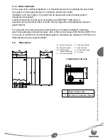
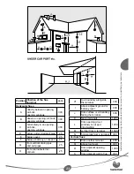
H*: This dimension comply with the 
building regulations, but it may need to
be increased to avoid wall staining and 
nusance from pluming depending on site 
conditions.

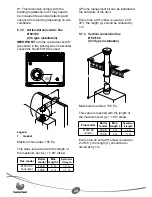
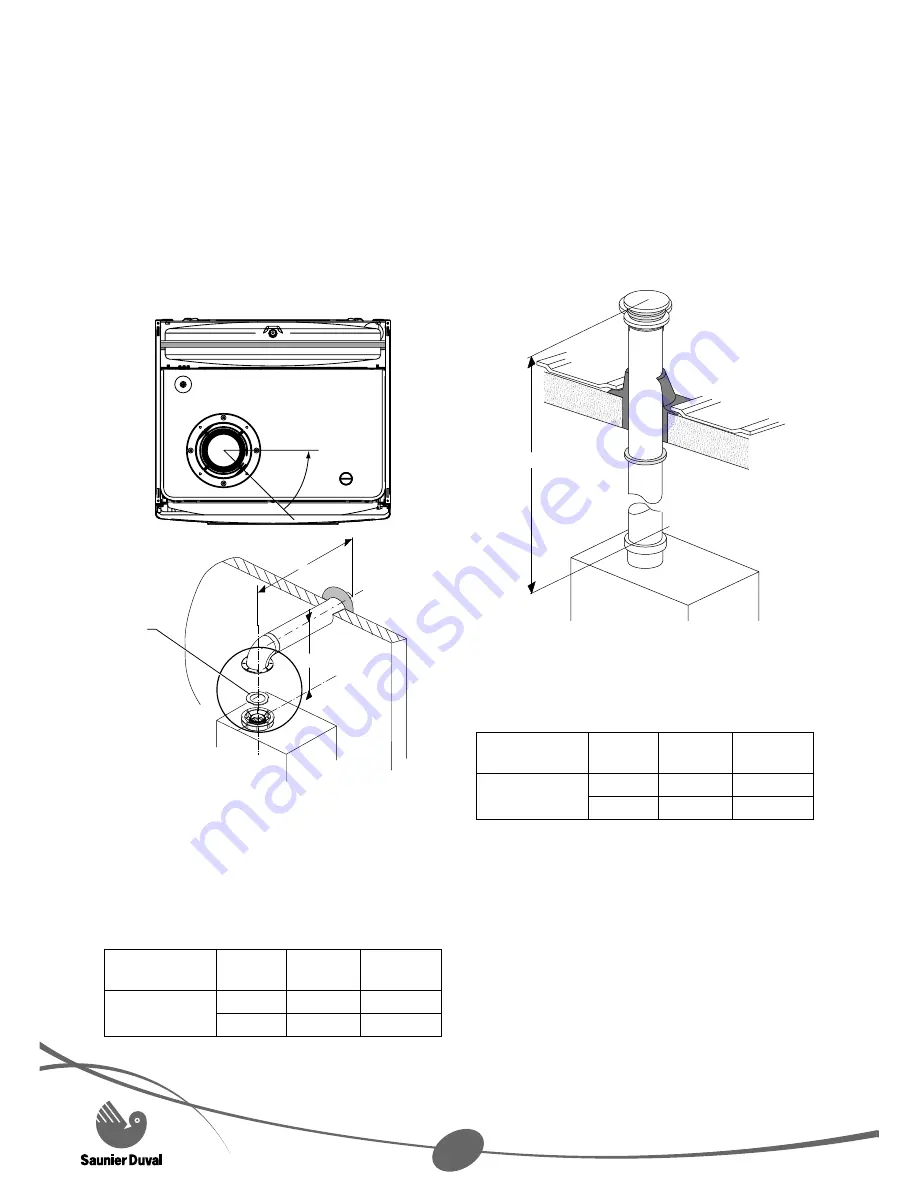
5.7.2 Horizontal 

concentric 

fl ue 

Ø 60/100  
(C13 type installation)

IMPORTANT: 

turn the coaxial socket 45° 

(as shown in the picture) when horizontal 
concentric fl ue Ø 60/100 is used.

1035_R01

45°

1

L

72

1034_R00

Legend
1 Gasket

Maximum fl ue index: 150 Pa

This value is reached with the length of 
the maximum duct (L) + 1 90° elbow.

Flue model

Boiler 

model

Max. 

length L

Restrictor 

if length

Ø 60/100

horizontal

F24 E

4 m

< 2 m

F30 E

3 m

< 1 m

A Plume mangement kit can be installed at 
the extremity of the duct.

Every time a 90° elbow is used (or 2 off 
45°), the length (L) should be reduced by 
1 m.

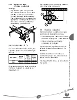
5.7.3 Vertical 

concentric 

fl ue 

Ø 60/100  
(C33 type installation)

L

Maximum fl ue index: 150 Pa

This value is reached with the length of 
the maximum duct (L) + 1 90° elbow.

Flue model

Boiler 

model

Max. 

length L

Restrictor 

if length

Ø 60/100

vertical

F24 E

5 m

< 2 m

F30 E

4 m

< 1 m

Every time an extra 90° elbow is used (or 
2 off 45°), the length (L) should be re-
duced at by 1 m.

Summary of Contents for Semia Condens F24 E

Page 1: ...HIGH EFFICIENCY CONDENSING COMBINATION BOILER Instructions for use Installation and servicing Semia Condens F24 E G C 47 920 51 Semia Condens F30 E G C 47 920 52...

Page 2: ......

Page 3: ...5 Recycling 4 6 Operating the boiler user instructions 5 6 1 Control panel 5 6 2 Commissioning and lighting 5 6 3 To program daily timeclock 5 6 4 Temperature adjustment 6 7 Turn the boiler off 6 8 Fa...

Page 4: ...ber States relating to electrical equipment designed for use within certain voltage limits 3 Directive 89 336 EEC on the approximation of the Laws of the Member States relating to electromagnetic comp...

Page 5: ...e but where the condition is not met any chargeable spare parts of components issued within the applicable guarantee period still bene t from a 12 month warranty from the date of issue by the manufact...

Page 6: ...le for any damage caused by another use In that case the user shall be the responsible party 4 Servicing Clean the case of the appliance with wet soapy cloth Do not use any abrasive cleaning product a...

Page 7: ...e control panel turns on the boiler is ready to run Turn the selector 2 to modify the operating mode of the boiler Central heating and domestic hot water Domestic hot water only Installer mode 0 reset...

Page 8: ...nd Anti Blocking functions can t be acti vated prevents damage to boiler during long period of inactivity The external general switch could be off FLASHING slowly the boiler has power but the SUMMER W...

Page 9: ...eral times with the SUMMER WINTER Selec tor on the 0 reset position until the red led turns off Code 01 Ignition problems if no work has been carried out Ensure that the SUMMER WINTER selector is on t...

Page 10: ...ance Move the SUMMER WINTER Selector on the 0 reset position until the red led turns off this may take a while to allow the boiler to cool Once the led is off move the selector to the desired position...

Page 11: ...f the appliance in the section reserved for installers in this manual 10 Maintenance After Sales Service Please note that an incorrectly serviced appliance can affect the safety of the appliance and c...

Page 12: ...delivered equipment 18 5 4 Fixing to the wall 18 5 5 Gas and water connection 19 5 6 Connection to the condensate trap 20 5 7 Flue connection 22 5 7 1 Flue restrictor 22 5 7 2 Horizontal concentric fl...

Page 13: ...ation 38 13 Spare parts 38 14 Maintenance 39 14 1 Casing 39 14 2 Combustion chamber 39 14 3 Burner 39 14 4 Heat exchanger 39 14 5 Reassembly of parts removed for servicing 40 14 6 Flue system 40 14 7...

Page 14: ...to appliances burning gaseous fuels Directive 73 23 EEC on the harmonisation of the Laws of the Member States relating to electrical equipment designed for use within certain voltage limits Directive...

Page 15: ...OW green OUTLET black INLET white CONDENSE orange FLUE WARNING This schematic is for information only 3 Appliance location This appliance is not suitable for outdoor installation This appliance may be...

Page 16: ...is could damage the appliance Under no circumstances must the User interfere with or adjust sealed parts Under Section 6 of The Health and Safety at Work Act 1974 we are required to provide informatio...

Page 17: ...Current I E E Wiring Regulations Where no speci c instructions are given reference should be made to the relevant British Standard Code of Practice In IE the installation must be carried out by a comp...

Page 18: ...r that is really required without taking into account the maximum power that the boiler can supply Nevertheless we advise you to have a ow big enough so that the temperature difference between outgoin...

Page 19: ...mander corrosion guard cleaner For long term corrosion protection after ushing an inhibitor suitable for stainless steel heat exchangers should be used refer to the current issue of BS 5449 and BS 759...

Page 20: ...pe 1 gas conversion instructions sheet 1 log book 1 condense drain pipe a set of 1 2 in gaskets a set of 3 4 in gaskets One pipe pack 2 central heating pipes 2 gas cold water pipes 1 hot water pipe a...

Page 21: ...foreign bodies may enter the boiler and disrupt the operation Do not use any solvents that could damage the heating circuit Do not brase the nozzles set on place this operation could damage the seals...

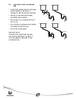
Page 22: ...w Use the condensate drain exible connection pipe supplied Ensure there is a conbinual fall of 2 5 44 mm m Do not let the condensate drain exible connection fall into the trap Do not use copper pipes...

Page 23: ...Installation and servicing instructions strictly reserved for quali ed gas installers 21 1041_R00...

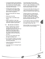
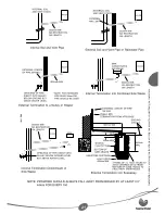
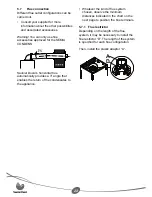
Page 24: ...s horizontal ue automatically provides a 3 angle that enables the return of the condensates to the appliance Whatever the kind of ue system chosen observe the minimum distances indicated in the chart...

Page 25: ...below eaves 25 F below a balcony or car port 25 G from vertical drain pipes and soil pipes 25 H from internal external corners 25 H to a boundary alongside the terminal 300 I above adjacent ground or...

Page 26: ...th of the maximum duct L 1 90 elbow Flue model Boiler model Max length L Restrictor if length 60 100 horizontal F24 E 4 m 2 m F30 E 3 m 1 m A Plume mangement kit can be installed at the extremity of t...

Page 27: ...odel Max length L1 L2 L2 Restrictor if length L1 L2 80 twin F24 E 10 9 m always F30 E 10 9 m always Every time an extra 90 elbow is used or 2 off 45 the length L should be re duced by 0 5 m For separa...

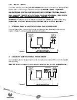
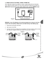
Page 28: ...is required it must be connected to the external controls lead as shown in gure 1 using a suitable electrical connection Figure 1 BOILER BLACK MAINS LEAD WHITE EXTERNAL CONTROL LEAD FUSED MAINS SPUR...

Page 29: ...Internal time clock factory fitted disconnected External potential free chrono thermostat 617B CHRONOTHERMOSTAT REMARK In case of installation of an external programmer see gure 2 and 3 the internal...

Page 30: ...F1 Fuse 2 A TA Voltage free contact for room Thermo stat or Cronothermostat Colour abbreviations BK Black BN Brown BU Blue GN Green GNYE Green Yellow GY Grey OG Orange RD Red VT Violet WH White TC Sy...

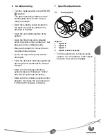
Page 31: ...r pressure on the indicator cold Bleed each radiator to remove the air re tighten bleed screws Leave the cap on the pump auto air vent open Flush the domestic hot water system by opening the hot water...

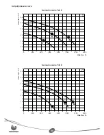
Page 32: ...0 5 1 1 5 2 2 5 3 3 5 4 4 5 5 5 5 6 0 200 400 1000 1200 600 800 1400 977 R00 Water flow l h Pressure m H 2 O Semia Condens F30 E 0 0 5 1 1 5 2 2 5 3 3 5 4 4 5 5 5 5 6 6 5 7 0 200 400 1000 1200 600 800...

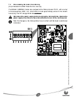
Page 33: ...P C B with an array of 8 microswitches SW3 1 8 which allow to make personalizing actions for the boiler s functioning The firm arrangements are underlined Disconnect the power supply before touching t...

Page 34: ...mines the extinction and new ignition temperature for DHW OFF Burner OFF at 75 C and burner ON at 70 C ON burner OFF at the arranged temperature for DHW T SET 5 C and burner ON at T SET this arrangeme...

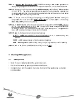
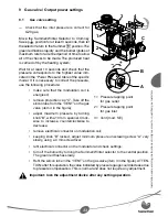
Page 35: ...on coil is energised remove protection cap C Take off the silicon tube from the VENT on the gas valve item 3 in the gure adjust maximum pressure by turning knob B with a 10 mm spanner Clock wise to in...

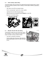
Page 36: ...ion Light the burner and check the gas pressure Adjust the pressure using potentiometer P1 MAX R on the PCB Re t cover to controls housing CONTROLS HOUSING 701_1_R00 PCB 704_R01 9 3 Domestic hot water...

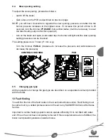
Page 37: ...light and the slow opening setting pressures can be checked The setting pressure is 7 mbar 71 mm w g Turn the trimmer P4 RLA clockwise to increase the pressure and anticlockwise to decrease the pressu...

Page 38: ...g system come NO water supply through the tap turned on YES Flow rate regulator turned off or boiler inlet filter dirty YES f Clean or replace the diaphragm inside domestic water priority valve If not...

Page 39: ...r correct gas pressure Check on the PCB the after a few seconds replace the NTC 60 C 2 5 k 80 C 1 3 k switches 7 and 8 are set to OFF YES TURN OFF THE HOT WATER TAP TURN THE MAIN SELECTOR TO WINTER SE...

Page 40: ...re that the user knows how to use the appliance Points to explain Explain to the user the appliance operating principles and demonstrate if required Have a look at the operating instructions together...

Page 41: ...er 14 3 Burner Undo main gas supply nut from burn er Pull main burner forward pull off the ignition and ame sense leads from the electrodes and remove burner from boiler Note The washer between main b...

Page 42: ...ect power supply and earth leads to fan Slacken but do not remove two screws securing fan to rear of ue hood Supporting fan unscrew and remove two screws securing fan to front of ue hood Lower fan fro...

Page 43: ...es on ow and return connections Re ll vent and pressurise boiler Check for leaks 15 4 To replace gas valve 1 Isolate boiler from gas supply Gain access to the gas valve by lower ing the controls panel...

Page 44: ...es on ow and return connections re ll vent and pressurise boiler Check for leaks Open cold water isolating valve Check for leaks 15 6 To replace thermistor Locate thermistor clipped onto ow pipe behin...

Page 45: ...hot water temperature C 80 80 Heating Heating temperature range standard C 30 80 30 80 Heating temperature range low temp C 25 45 25 45 Expansion vessel useful capacity l 8 8 Expansion tank initial p...

Page 46: ...r 20 20 Burner injector diameter mm 1 25 1 30 1 15 C 1013 25 mbar 16 1 Burner pressure tables SEMIA CONDENS F24 E HEAT OUTPUT PRESSURE kW Btu hr mbar 9 5 32566 2 1 10 34120 2 3 11 37532 2 7 12 40944 3...

Page 47: ...exchanger 8 Flame sense electrode 9 Ignition electrode 10 Burner 11 Water valve 12 Gas valve 13 Syphonic condensate trap 14 Domestic plate to plate heat exchanger 15 Hydraulic 3 way valve 16 Low press...

Page 48: ......

Page 49: ......

Page 50: ...982790002 000...

Page 51: ......

Page 52: ...10 2005 982 160099 001 Saunier Duval Nottingham Road Belper Derbyshire DE56 1JT Tel 00 44 0 1773 525914 Fax 00 44 0 1773 828070 www saunier duval co uk...

Reviews: