background image

11

SAFETY DEVICES

Flue safety device

If an obstruction, even
partial, of the flue oc-
curs, for any reason
whatsoever, the built in
flue safety device will
turn the boiler OFFand
the warning LED on the

Sec 055

In case of loss of water in
the system

CAUTION. The boiler is in-
stalled as part of a sealed
system which must only be
drained and filled by a
competent person.
If the pressure shown on
the pressure gauge, 

see

diagram 16

, is less than 1 bar, the system must be

filled up immediately. Call your  Installer/Service
Provider.

Overheat safety

In the event of a problem, the overheat safety
device cause safety shutdown of the boiler. If this
happens, call your Installer/Service Provider.

Frost protection

The 

THEMA C 23 

boiler

has a built in  frost pro-
tection device that pro-
tects the boiler from
freezing. If the boiler is to
be left and there is a risk
of frost, ensure that the
gas and electrical sup-

Diagram 17

plies are left connected and that the Summer/Win-
ter switch is in the 'Summer' position.

The frost protection device will light the boiler when
the temperature of the boiler water falls below 6

°

C.

When the temperature reaches 16

°

C, the boiler

stops.

Note: 

This device works irrespective of any room

thermostat setting and only protects the boiler.

Important notice

: Under no circumstances must the

flue safety device be bypassed or removed. Any
repairs on the flue safety device must be carried
out by a qualified engineer using genuine replace-
ment parts only.

Air in the heating system

Persistent air in the heating system may indicate
leaks in the system or corrosion taking place. Call
your Installer/Service Provider.

Gas leak or fault

If a gas leak or fault exists or is suspected, turn the
boiler off and consult the local gas undertaking or
your Installer/Service Provider.

In case of power supply failure

The boiler no longer operates.
As soon as power supply is restored, the boiler will
be automatically restarted.

Important notice: 

A central heating system cannot

operate satisfactorily unless it is properly filled with
water and unless the air initially contained in the
piping systems has been properly bled off. If these
conditions are not satisfied, air noise will occur
within the system.

Sec 056

SETTINGS

Bypass

The built-in bypass must be adjusted according to
the requirements of the system. Refer to the flow
rate/pressure curve (

diagram 3

). The boiler is sup-

plied with the bypass open half a turn. It is adjusted
by turning the bypass screw, 

see diagram 18

. Turn

the screw clockwise to close the bypass.
When using thermostatic radiator valves (TRV's), it
is advisable to fit a separate, adjustable bypass of
15 mm minimum diameter between the flow and
return connections of the heating circuit. Any by-
pass must be fitted before system controls.

Pump operation in heating mode

The PCB can be set to operate the pump in two
ways, 

see diagram 19.

Position D: Intermittent pump operation.

With the jumper set to position 'D', the pump will
operate during operation of the room thermostat.

Position C: Continuous pump operation.

With the jumper set to position 'C', the pump will
operate continuously.

Reg 013

Reg 004

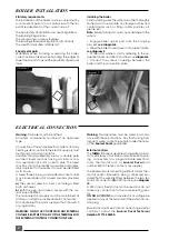
Diagram 15

boiler control panel will light. If this occurs, contact
your Installer/Service Provider.

Diagram 16

Diagram 18

Diagram 19

Summary of Contents for THEMA C 23

Page 1: ...eating and hot water for the professionals THIS IS A CAT II2H3 APPLIANCE 01773 828100 I N W A R R A N T Y T E C H N I C A L H E L P L I N E 01773 828400 THEMA C 23 Installation and Servicing Instructi...

Page 2: ...English market The identification plate located on the inside of the appliance certifies the origin where the product was manufactured and the country for which it is intended If you see any exceptio...

Page 3: ...nd standards currently in force for this type of boiler Both the central heating and domestic hot water temperature are user adjustable from the boiler control panel see diagram1 Electrical components...

Page 4: ...Inlet pressure 20 mbar 28 mbar 37 mbar Gas rate maximum 2 71 m3 h 2 02 kg h 1 99 kg h Gas rate minimum 1 11 m3 h 0 83 kg h 0 82kg h Pump The performance of the pump varies according to the pump bypass...

Page 5: ...Pump 10 Automatic air vent 11 Burner 12 Heat exchanger bleed pipe 13 Heat exchanger 14 Gas valve Diagram 4 16 Overheat thermostat 17 Ignition electrode 18 Pilot 19 High limit thermostat 21 Loss of wa...

Page 6: ...s than 15 m o d pipe to discharge in a visible position outside the building facing downward preferably over a drain The pipe must have a con tinuous fall and be routed to a position so that any disch...

Page 7: ...or Sen tinel Contact the product manufacturers for specific details Filling the system Provision must be made for filling the system at low level The use of a WRC approved filling loop is strongly rec...

Page 8: ...er The boiler will work for heating without a room ther mostat and or timeswitch being connected pro vided that the wire link fitted between the two ter minals of connector E is left in place see diag...

Page 9: ...pressurise system as necessary Important If this procedure is not carried out properly the boiler will go into safety lock out until all of the air has been purged When venting air from boiler do not...

Page 10: ...sure test point below sealed combustion chamber see diagram 14 Connect a suitable pressure gauge Gain access to the rear of the control panel and locate the range rating adjuster screw see dia gram 13...

Page 11: ...ystem may indicate leaks in the system or corrosion taking place Call your Installer Service Provider Gas leak or fault If a gas leak or fault exists or is suspected turn the boiler off and consult th...

Page 12: ...olding both sides pull chamber forward to re lease it from underside of heat exchanger and out of boiler Take care not to damage insulation material on inside faces of combustion chamber Cleaning the...

Page 13: ...retaining clip from telescopic pump out let connection and slide connection upwards to release from pump Undo and remove two fixing screws and remove pump retaining bracket from front of pump Grasp p...

Page 14: ...fit expansion vessel pipe and loss of water switch to reversing valve assembly before pump to ensure that it is correctly located Apply silicone grease to all O rings and hoses prior to assembly Open...

Page 15: ...five screws and separate main components of water valve If white diaphragm cover is to be replaced sepa rate original from water valve end casting and fit replacement cover Fit replacement diaphragm m...

Page 16: ...between gas valve and burner supply pipe Refit push button box and thermocouple Refit electrical connections to replacement gas valve To replace modulating coil Ensure gas supply is off Disconnect two...

Page 17: ...place overheat thermostat Locate overheat thermostat on right hand side of heat exchanger REPLACEMENT OF PARTS Pull off electrical connections from thermostat Unscrew and remove two screws holding the...

Page 18: ...estic hot water works correctly but the heat ing doesn t refer to chart No 1 If heating works correctly but the hot water doesn t refer to chart No 3 IMPORTANT Always adopt a logical step by step pro...

Page 19: ...ostat operating correctly i e two stage operation of burner by rotating knob Replace boiler thermostat Replace main PCB NO NO YES YES YES YES NO NO YES NO FAULT FINDING Thermistor values Temperature o...

Page 20: ...mistor ok Refer to chart no 1 Check mains water supply water filter Replace diaphragm Replace DHW microswitch Replace DHW thermistor Replace PCB NO NO NO NO NO NO YES YES YES YES YES CHART 3 NO HOT WA...

Reviews: