background image

8

ELECTRICAL CONNECTION

Warning. 

This boiler must be earthed

All system components must be of an approved
type.

Connection of the whole electrical system and any
heating system controls to the electrical supply must
be through a common isolator.
Isolation should preferably be by a double pole
switched fused spur box having a minimum con-
tact separation of 3 mm on each pole. The fused
spur box should be readily accessible and prefer-
ably adjacent to the boiler. It should be identified
as to its use.
A fused three pin plug and shuttered socket outlet
may be used instead of a fused spur box provided
that:

a)

 They are not used in a room containing a fixed

bath or shower.

b)

 Both the plug and socket comply with the cur-

rent issue of BS1363.
The mains electrical supply must be maintained at
all times in order to provide domestic hot water.
Do not interrupt the mains supply with a time switch
or programmer.

WARNING: ON NO ACCOUNT MUST ANY EXTERNAL
VOLTAGE BE APPLIED TO ANY OF THE TERMINALS ON
THE EXTERNAL CONTROLS CONNECTION PLUG.

Warning

: This appliance must be wired in accord-

ance with these instructions. Any fault arising from
incorrect wiring cannot be put right under the terms
of the

 Saunier Duval 

guarantee.

External controls

The 

THEMA C 

boiler is designed to operate at maxi-

mum efficiency at all times and will benefit by be-
ing  connected to a programmable electronic
room thermostat such as 

Saunier Duval 

part

number 40010. Please contact your supplier.

The boiler will work for heating without a room ther-
mostat and/or timeswitch being connected pro-
vided that the wire link fitted between the two ter-
minals of connector 

(E)

 is left in place, see 

diagram

10.

A 230V room thermostat can be used but do not
make any connection to the compensating resis-
tor.

ON NO ACCOUNT

 must any electrical voltage be

applied to any of the terminals of the external con-
trols plug.

Should any doubt exist about connecting external
controls, contact the 

Saunier Duval Technical

Helpline 01773 828400.

BOILER INSTALLATION

Statutory requirements

The installation of this boiler must be carried out by
a competent person in accordance with the rel-
evant requirements of the current issue of:

The Gas Safety (Installation and Use) Regulations
The Building Regulations
The local water company Byelaws
The Building Standards Regulations (Scotland)
The Health and Safety at Work Act

Sheet metal parts

WARNING. When installing or servicing this boiler,
care should be taken when handling the edges of
sheet metal parts to avoid the possibility of personal
injury.

Installing the boiler

Prior to starting work, the system must be thoroughly
flushed so as to eliminate any foreign bodies and
contaminants such as filings, solder particles, oil,
grease etc.

Note. 

Solvent products could cause damage to the

system.

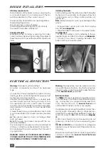
• Engage boiler upper part onto the hanging
bracket, 

see diagram 8.

• Allow the boiler to seat down onto support plate,

see diagram 9.

• Fit filter and washers, strictly adhering to the se-
quential order and directions shown on 

diagram 5.

• Connect the various couplings between the
boiler and the connection plate.

Ins 020

Ins 021

Diagram. 8

Diagram. 9
Summary of Contents for THEMA C 23

Page 1: ...eating and hot water for the professionals THIS IS A CAT II2H3 APPLIANCE 01773 828100 I N W A R R A N T Y T E C H N I C A L H E L P L I N E 01773 828400 THEMA C 23 Installation and Servicing Instructi...

Page 2: ...English market The identification plate located on the inside of the appliance certifies the origin where the product was manufactured and the country for which it is intended If you see any exceptio...

Page 3: ...nd standards currently in force for this type of boiler Both the central heating and domestic hot water temperature are user adjustable from the boiler control panel see diagram1 Electrical components...

Page 4: ...Inlet pressure 20 mbar 28 mbar 37 mbar Gas rate maximum 2 71 m3 h 2 02 kg h 1 99 kg h Gas rate minimum 1 11 m3 h 0 83 kg h 0 82kg h Pump The performance of the pump varies according to the pump bypass...

Page 5: ...Pump 10 Automatic air vent 11 Burner 12 Heat exchanger bleed pipe 13 Heat exchanger 14 Gas valve Diagram 4 16 Overheat thermostat 17 Ignition electrode 18 Pilot 19 High limit thermostat 21 Loss of wa...

Page 6: ...s than 15 m o d pipe to discharge in a visible position outside the building facing downward preferably over a drain The pipe must have a con tinuous fall and be routed to a position so that any disch...

Page 7: ...or Sen tinel Contact the product manufacturers for specific details Filling the system Provision must be made for filling the system at low level The use of a WRC approved filling loop is strongly rec...

Page 8: ...er The boiler will work for heating without a room ther mostat and or timeswitch being connected pro vided that the wire link fitted between the two ter minals of connector E is left in place see diag...

Page 9: ...pressurise system as necessary Important If this procedure is not carried out properly the boiler will go into safety lock out until all of the air has been purged When venting air from boiler do not...

Page 10: ...sure test point below sealed combustion chamber see diagram 14 Connect a suitable pressure gauge Gain access to the rear of the control panel and locate the range rating adjuster screw see dia gram 13...

Page 11: ...ystem may indicate leaks in the system or corrosion taking place Call your Installer Service Provider Gas leak or fault If a gas leak or fault exists or is suspected turn the boiler off and consult th...

Page 12: ...olding both sides pull chamber forward to re lease it from underside of heat exchanger and out of boiler Take care not to damage insulation material on inside faces of combustion chamber Cleaning the...

Page 13: ...retaining clip from telescopic pump out let connection and slide connection upwards to release from pump Undo and remove two fixing screws and remove pump retaining bracket from front of pump Grasp p...

Page 14: ...fit expansion vessel pipe and loss of water switch to reversing valve assembly before pump to ensure that it is correctly located Apply silicone grease to all O rings and hoses prior to assembly Open...

Page 15: ...five screws and separate main components of water valve If white diaphragm cover is to be replaced sepa rate original from water valve end casting and fit replacement cover Fit replacement diaphragm m...

Page 16: ...between gas valve and burner supply pipe Refit push button box and thermocouple Refit electrical connections to replacement gas valve To replace modulating coil Ensure gas supply is off Disconnect two...

Page 17: ...place overheat thermostat Locate overheat thermostat on right hand side of heat exchanger REPLACEMENT OF PARTS Pull off electrical connections from thermostat Unscrew and remove two screws holding the...

Page 18: ...estic hot water works correctly but the heat ing doesn t refer to chart No 1 If heating works correctly but the hot water doesn t refer to chart No 3 IMPORTANT Always adopt a logical step by step pro...

Page 19: ...ostat operating correctly i e two stage operation of burner by rotating knob Replace boiler thermostat Replace main PCB NO NO YES YES YES YES NO NO YES NO FAULT FINDING Thermistor values Temperature o...

Page 20: ...mistor ok Refer to chart no 1 Check mains water supply water filter Replace diaphragm Replace DHW microswitch Replace DHW thermistor Replace PCB NO NO NO NO NO NO YES YES YES YES YES CHART 3 NO HOT WA...

Reviews: