background image

51.362/6  

AVM 105S...115S


Sauter Components 


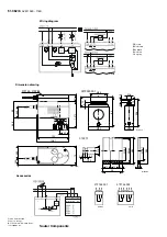
Wiring diagram 


A10450

RD = red 
BN = brown 
BK = black 
BU = blue 
GY = grey


Dimension drawing 


0372249 001

Ø42

5

15

60

Ø33

Ø8

3,

2

10

2,

5

55

,8

Ø16

Z10214

43

,5

35

M09743b

122

10

7,

1

70

46

,5

23

,5

126,7

63

45

,6

32

372145, 372286

372273

M10203

Ø3

3

Ø2

6

,7

SW

3

0

Ø3

3

Ø2

6

,5

8

10

10

4

24

15,5

3,2

2,5

Ø8


Accessories 


MM 01/02

03

372145 002 

372145 001 

A09782

RD BN BK

A10183

RD BN BK GN GY VT

Printed in Switzerland 
Subject to change.  
© Fr. Sauter AG. CH-4016 Basle 
7151362003  05 

Summary of Contents for AVM 105S

Page 1: ... fitting valve Connecting cable 1 2 m long 5 0 75 mm Installation position vertical to horizontal but not upside down 100 0 V Output signal y 10 V B07650 0 D i r e c t i o n o f o p e r a t i o n 2 D i r e c t i o n o f o p e r a t i o n 1 Type Running time s Stroke 2 mm Pushing force N Power Weight kg For valves with equal percentage characteristic can be switched over to linear AVM 105S F132 35 ...

Page 2: ... of stroke is attained with 1 turns N B After manual adjustment re set the sliding switch engage the transmission Connected as a 2 point actuator Open close activation can be effected via two wires Power is applied to the drive via the blue and the brown wires On connecting power to the black wire the valve s control passage opens When power is switched off the drive goes to the opposite end posit...

Page 3: ...valve s characteristic can be selected using the coding switch The characteristics can be generated only if the drive is used as a continuous drive Other switches enable the running times to be set These can be applied irrespective of which function 2 point 3 point or continuous has been chosen Coding switch for setting the running time AVM 105S 7 5 s 60 s 2 15 s 120 s 4 B10703 On Off On Off 1 2 3...

Page 4: ...artial range is amplified into an output signal of 0 10 V This accessory cannot be fitted in the actuator but should be located externally in an electric distribution box CASE Drives PC tool accessory 0372462 001 CASE Drives enables all the actuator s parameters to be set and viewed on site Connection is via a serial port on the PC laptop and a socket on the actuator The set comprises software inc...

Page 5: ...ches are accessible via an opening with black lid in the housing cover The auxiliary contacts should be screwed onto the drive s top cover Before the mechanical connection can be established the indicator knob should be removed A new indicator is then visible on the lid of the auxiliary contacts N B The housing should not be opened Fitting outdoors If the devices are fitted outdoors we recommend t...

Page 6: ... 60 Ø33 Ø8 3 2 10 2 5 55 8 Ø16 Z10214 43 5 35 M09743b 122 107 1 70 46 5 23 5 126 7 63 45 6 32 372145 372286 372273 M10203 Ø33 Ø26 7 SW30 Ø33 Ø26 5 8 10 10 4 24 15 5 3 2 2 5 Ø8 Accessories MM 01 02 03 372145 002 372145 001 A09782 RD BN BK A10183 RD BN BK GN GY VT Printed in Switzerland Subject to change Fr Sauter AG CH 4016 Basle 7151362003 05 ...

Reviews: