CLI-8000 | 009-1090-03 | 161006
Copyright© 2016 Savant Systems, LLC
45 Perseverance Way, Hayannis, MA 02601
Savant.com
| 508.683.2500
Mounting
The CLI-8000 can be either surface mounted using a pair of mounting
brackets (SMB-8000-xx) or flush mounted between two 16 inch on
center studs. For more information on mounting, refer to the CLI-8000
Deployment Guide (009-1073-xx).
Flush Mount (between studs)
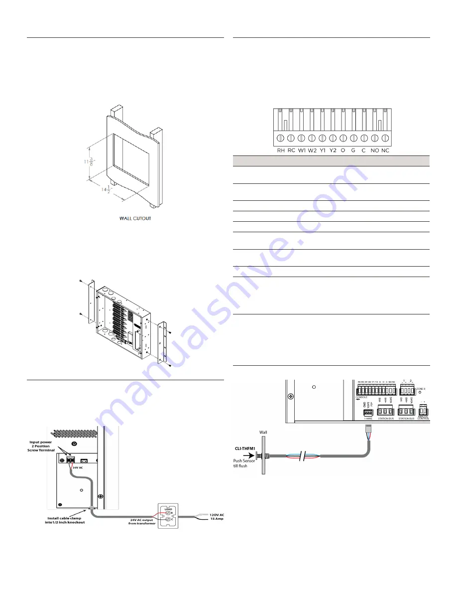
1. Locate two adjacent studs that are 16 inch on center. If there is
drywall, cut to the dimensions below.
2. Slide between studs. On left and right side there are three mount-
ing holes. Screw to inside of studs through these holes.
Surface Mount (Optional Brackets)
1. Screw the mounting brackets to the right and left side of the CLI-
8000 using (4) 10-32 x ⅜ inch FH machine screws.
2. The mounting brackets are 16 inch on center so the TPU can be
screwed to two adjacent studs. Locate two adjacent studs that are
16 inch on center.
3. Screw the TPU to the wall through the drywall and into the studs
using appropriate self tapping drywall screws or equivalent.
Connect Input Power
1. Remove the access panel by removing the screw holding down the
access panel.
2. Locate the ½ inch electrical knockout just below access panel. Re-
move knockout and install electrical clamp.
3. Connect the 24V AC from transformer to the two position screw
terminal block under the power input panel.
Note
: Use a minimum of 18 AWG wire when connecting the input
power.
HVAC Relay Wiring
The figure below is the top view of the eleven position screw termi-
nal connector that is plugged into each relay bank. Ensure all power
from both the HVAC and CLI-8000 system have been removed before
making connections.
1. Remove connector from its mate on front panel.
2. Insert correct wire into front of plug using information in the table
below.
3. Tighten screw so that wires are clamped inside the connector.
4. Reinsert into the proper relay bank.
5. Wire other side to HVAC system.
Relay
Description
RH - Red
Wired to hot side of transformer on heating equip-
ment.
RC - Red
Wired to hot side of transformer on cooling equip-
ment.
W1 - White Wired to stage 1 heat terminal (W1) on HVAC system.
W2 - Black Wired to stage 2 heat terminal (W2) on HVAC system.
Y1 - Yellow
Wired to stage 1 cooling terminal (Y1) on HVAC system.
Y2 - Blue
Wired to stage 2 cooling terminal (Y2) on HVAC sys-
tem.
O - Orange Wired to (O) terminal on Heat Pump System.
Reversing Valve connection.
G - Green
Wired to fan terminal (G) on HVAC system.
C NO NC
C
= Common Terminal
NO
= Normally Open. Connects with C when the Relay
is ON.
NC
= Normally Closed. Connects with C when the
Relay is OFF.
There is no standard for wire colors in HVAC. The colors shown in table
are typical. Refer to manufacturer’s documentation for HVAC system
before wiring.
The Relays support an external voltage of 24V AC at 1 AMP.
Note
: If required, RH and RC can be jumped together.
Remote Sensor Connections
Wiring diagram connecting the CLI-THFM1 sensor to the CLI-8000. Up
to two CLI-THFM1 sensors per zone.
In addition to the CLI-THFM1 Smart Sensor described above, other
sensors are available. For information on the these sensors, refer to the
Quick Reference Guides (QRGs) for each sensor.
Additional Documentation
Refer to the following documents located on the
Savant Customer
Community
for additional information.
• CLI-8000 Deployment Guide (009-1073-xx)


