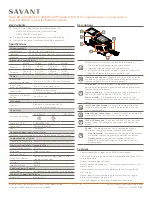
Dual 20 Amp Relay Companion Module - QRG | 009-2129-00
3 of 4
45 Perseverance Way, Hyannis MA 02601
Copyright ©2022 Savant Systems, Inc | 220408
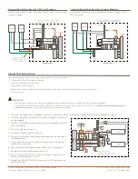
Circuit Test Instructions
Use the instructions below to test the relay modules. The setup requires:
–
20 Amp Dual Relay Companion Module.
–
(2) loads (20 amps max for each).
–
(2) 20 amp circuit breakers.
–
Breaker test panel. The type of module determines the type of breaker panel (plug-on neutral or not).
–
120V AC source
1. Plug the two feeder circuit breakers and one 20 Amp Dual Relay Companion Module into the circuit breaker test panel.
2. Connect the output from one of the circuit breakers to Input A
on the module.
3. Connect the output from the remaining circuit breaker to Input
B on the module.
4. Connect a load to Output A.
5. Connect a second load to Output B.
6. Connect the unused side of each load to the neutral bus bar in
the breaker panel.
7. On modules that contain a neutral wire, connect the neutral
wire to the neutral bar.
8. Apply power to the breaker panel (not shown in diagram).
9. Toggle the 20 amp feeder breakers to On.
10. To test, toggle the CIRCUIT POWER switches A and B to ON
and verify both loads switch On.
11. Toggle the CIRCUIT POWER switches to AUTO and verify the
loads switch Off
6
Load
Load
5
PANEL CIRCUIT
BREAKER
INPUT
OUTPUT
OUTPUT
A
INPUT
CIRCUIT PO
WER
ON
A
U
TO
PAIR
A
B
20A DU
AL RELA
Y
A
B
B
Plug-on neutral
bus bar for modules with
a Plug-On neutral clip
120VAC
PANEL CIRCUIT
BREAKER
2
1
3
4
7
9
10 11
IMPORTANT!
–
When making connections, observe all general electrical best practices including local wire sizing guidelines.
–
The GPM-CP2R20120-21 and GPM-C2R20120-21 modules can accept up to a #12 AWG wire. See the
Branch Circuit Minimum Size of
Conductors
table on the previous page for wire sizing information.
Standard
Neutral Bus Bar with ARC Fault Breakers
Standard Neutral Bus Bar with Standard Breakers
Neutral Bar
Neutral wire from the
companion module connects
to the neutral bar
Phase A
Phase B
Breaker Panel
Gnd
Bar
Use AFCI / GFCI protection where
required by local regulations
INPUT
OUTPUT
OUTPUT
B
A
B
A
INPUT
CIRCUIT PO
WER
ON
A
U
TO
PAIR
A
B
20A DU
AL RELA
Y
BREAKER
BREAKER
Load 1
Load 2
120VAC
Neutral Bar
Breaker Panel
Gnd
Bar
120VAC
Phase A
Phase B
Use AFCI / GFCI protection where
required by local regulations
INPUT
OUTPUT
OUTPUT
B
A
B
A
INPUT
CIRCUIT PO
WER
ON
A
U
TO
PAIR
A
B
20A DU
AL RELA
Y
BREAKER
BREAKER
Load 1
Load 2
Breaker panel without a plug-on neutral bus bar (with ARC Fault type
feeder breakers).
Breaker panel without a plug-on neutral bus bar and standard type
feeder breakers.


