Dual 20 Amp Relay Companion Module - QRG | 009-2129-00
2 of 4
45 Perseverance Way, Hyannis MA 02601
Copyright ©2022 Savant Systems, Inc | 220408
–
The breaker(s) feeding the module should not be larger than 20 amps.
–
Each relay output can switch up to 20 amps.
–
To determine the number of breaker panel spaces needed, add the number of spaces required for the circuit breaker(s) to the number of
spaces needed for the module.
• A single pole circuit breaker requires one space.
• A 2-pole circuit breaker requires two spaces.
• Each Companion Module requires two spaces.
–
Savant recommends not connecting any mission-critical loads such as medical devices to this relay module.
Important Information
ELECTRIC SHOCK!
The 120V AC, 60 Hz source poses an
electrical shock hazard that has the potential to cause serious
injury to installers and end users.
CAUTION!
Risk of Electric Shock - More than one disconnect
switch may be required to de-energize the device before
servicing
IMPORTANT!
A licensed electrician is required to install any of
Savant’s Relay Companion Modules.
1. Remove power from the breaker panel by switching off the panel’s main breaker.
2. Position and install a circuit breaker into one of the slots in the panel. Press firmly until the breaker is fully seated onto the appropriate bus
bars.
3. Install a second breaker alongside the first.
4. Position and install the Companion Relay Module into the slot where it will be installed. Press firmly until fully seated onto the appropriate bus
bars. This module is typically installed alongside the breakers installed in steps 2 and 3.
HELPFUL!
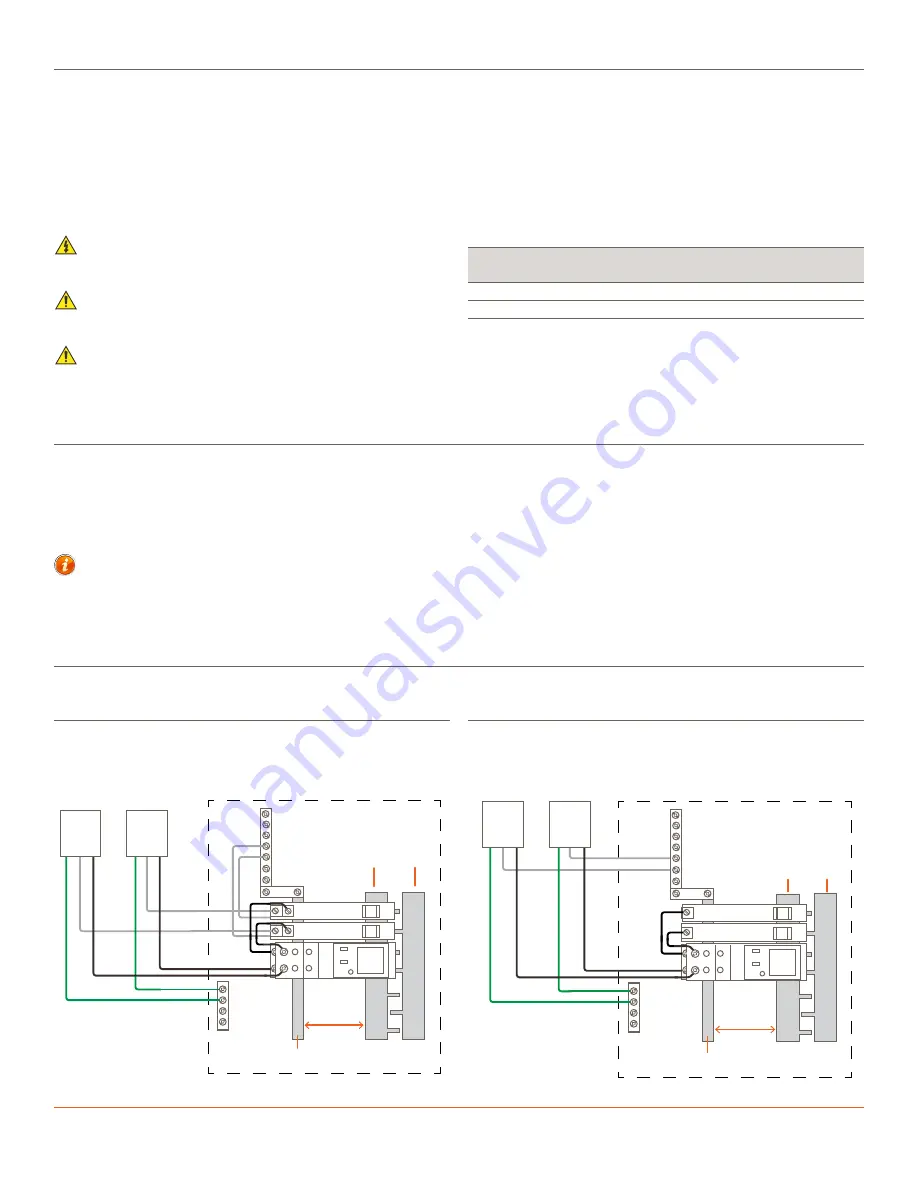
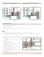
A relay module fills two slots in the breaker panel but connects to only one phase (120V AC). See the diagram below.
5. Refer to the
section below and make the appropriate connections.
Installation into Breaker Panel
Branch Circuit Minimum Size of Conductors
(General circuit wiring, Copper Conductors)
15A
20A
30A
40A
50A
60A
#14 AWG
#12 AWG
#10 AWG
#8 AWG
#6 AWG
#4 AWG
NOTE:
This wiring requirement was based on the National Electric Code
(NEC) (ANSI/NFPA70), Canadian Electric Code, Part 1 (CEC), and local
codes Minimum Size of Conductors.
Plug-on Neutral Bus Bar with ARC Fault Breakers
Wiring
Plug-on Neutral Bus Bar with Standard Breakers
Neutral Bar
Phase A
Phase B
Breaker Panel
Gnd
Bar
120VAC
plug-on
neutral bar
Use AFCI / GFCI protection where
required by local regulations
INPUT
OUTPUT
OUTPUT
B
A
B
A
INPUT
CIRCUIT PO
WER
ON
A
U
TO
PAIR
A
B
20A DU
AL RELA
Y
BREAKER
BREAKER
Load 2
Load 1
Neutral Bar
Breaker Panel
Gnd
Bar
120VAC
plug-on
neutral bar
Phase A
Phase B
Use AFCI / GFCI protection where
required by local regulations
INPUT
OUTPUT
OUTPUT
B
A
B
A
INPUT
CIRCUIT PO
WER
ON
A
U
TO
PAIR
A
B
20A DU
AL RELA
Y
BREAKER
BREAKER
Load 2
Load 1
Use the diagrams below when wiring the modules. The diagrams cover the following scenarios:
Breaker panel with a plug-on neutral bus bar (with ARC Fault type
feeder breakers).
Breaker panel with a plug-on neutral bus bar (with standard type
feeder breakers).


