background image

Savant Power System Wiring and Installation Deployment Guide

Copyright 2022 Savant Systems, Inc

009-2222-02 |  080122

- 1 -

Savant Power System Wiring Guide

Wiring and Installation

Document Number:

009-2222-02

Document Date:

August 2022

Document Supports:

da Vinci 10.1 or higher

This document guides the installer through the process of wiring and configuring Savant Power System, and supports the following products:

Summary of Contents for PKG-200AMPKIT-00

Page 1: ...2 02 080122 1 Savant Power System Wiring Guide Wiring and Installation Document Number 009 2222 02 Document Date August 2022 Document Supports da Vinci 10 1 or higher This document guides the installer through the process of wiring and configuring Savant Power System and supports the following products ...

Page 2: ...AL CT and VT Placement 8 4 Savant Power Module Installation 9 4 1 120V 20A Dual Relay Power Modules 9 4 2 240V 30A Relay Power Modules 11 4 3 240V 60A Relay Power Module 12 5 Automatic Generator 13 5 1 Pro Host with Generator 13 5 2 Smart Host with Generator 14 6 Sol Ark HomeGrid 15 6 1 Savant Sol Ark Wiring 15 6 2 Sol Ark Low Voltage Single Inverter Battery AC 16 6 2 Sol Ark HomeGrid Single Batte...

Page 3: ...g of the device 9 If the provided plug does not fit the desired outlet contact a licensed electrician to replace the obsolete outlet 10 Protect any power cord from being walked on pinched strained or otherwise potentially damaged especially at the outlet or device connections 11 Disconnect any outlet powered apparatus from its power source during lightning storms or when unused for long periods of...

Page 4: ...atic Transfer Switches ATS must have Auxiliary Position Indicating Contacts to connect to the GPIO terminals on the Savant Host or Smart Controller Auxiliary Position Indicating Contacts come standard on all commonly sold Generac Model residential ATS Kohler residential ATS models RXT and RDT 300A and 400A can be purchased as an accessory for Kohler model ATS under 300A They can also be purchased ...

Page 5: ...h in turn is used for accurate information and active control To ensure that the correct data is transmitted the system must be installed according to the diagrams listed within this document IMPORTANT Complete sections 3 and 4 Skip all other sections that are unrelated to the specific installation type To successfully deploy a Savant Savant Power System follow the steps listed below This page can...

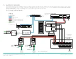
Page 6: ...ons and sending information to the Savant Host The Panel Bridge Controller relays commands sent by the Host over Bluetooth to Power Modules The Savant Power Panel contains all Power Modules paired with the Panel Bridge Controller and executes all commands sent to it VT CT RS232 Ethernet 1 2 IR 6 5 4 1 2 3 G G NC C2 NO NO C1 NC RELAY 12 VDC PD1PD2 SSC 0012 Savant Host Network Switch 1 2 3 4 5 6 7 8...

Page 7: ...1 12 13 14 15 N A VT CONNECTIONS A B C SmartEnergy Monitor To Home Network To BAT ATS AUX MODBUS TCP IP CAT5 STATIC SIGNAL TWISTED PAIR POSITIVE IP CAT 5 STATIC SIGNAL TWISTED PAIR NEGATIVE CAT5 WIRE DETAILS LEGEND GROUND NEUTRAL Reset Ethernet USB Audio RS232 1 RS232 2 1 IR 2 3 Relay C NC NO 4 5 6 5VDC GPIO SHR 2000 Panel Bridge Controller SAVANT POWER PANEL 20 o OFF CIRCUIT POWER ON AUTO PAIR A ...

Page 8: ...Power System with Generator SEM CT Physical Connection Circuit Name CT Size Classification 1 2 ATS Normal Input Grid Feed 250A Feed 3 4 ATS Emergency Input Generator Power 150A Production NOTE Generator circuit CT rating is inverted Savant Power System with Schneider ESS SEM CT Physical Connection Circuit Name CT Size Classification 1 2 ATS Input Grid Feed 250A Feed 3 4 ATS Output Total Consumptio...

Page 9: ...Module 4 1 120V 20A Dual Relay Power Modules GPM QP2R20120 21 ARC Fault Breakers IMPORTANT NOTES The 120V 20A Dual Relay Power Modules switches on and off loads A and B The main electrical panel contains ARC fault breakers See the next page for the standard non ARC fault breaker diagram The diagram shows connections for both a plug on neutral and pigtail neutral wire 120V 20A Dual Relay Power Modu...

Page 10: ...ads A and B The main electrical panel contains standard non ARC fault breakers See the previous page for a diagram using ARC fault breakers Load B Connect a Gnd wire to each load Ground Bar Main Electrical Panel Neutral Bar Neutral Bar INPUT OUTPUT OUTPUT B A B A INPUT CIRCUIT POWER ON AUTO PAIR A B 20A DUAL RELAY INPUT OUTPUT OUTPUT B A B A INPUT CIRCUIT POWER ON AUTO PAIR A B 20A DUAL RELAY BREA...

Page 11: ...aker supplies the 240V AC to the 240V 30A Relay Modules Neutral and ground wires on both load centers must be common respectively Ground Bar Ground Bar Main Electrical Panel L1 Neutral Bar Neutral Bar Neutral Bar Neutral Bar Connect a Gnd wire to load Power Module Panel Load 240V AC INPUT OUTPUT OUTPUT L2 L1 L2 L1 INPUT CIRCUIT POWER ON AUTO PAIR A 240VAC 2 POLE RELAY INPUT OUTPUT OUTPUT B A B A I...

Page 12: ...Module can accept up to a 4 AWG wire Connect a Gnd wire to each load Ground Bar Main Electrical Panel 240V AC Plug on neutral bar Phase A Phase B STANDARD BREAKER STANDARD BREAKER 2 POLE BREAKER Load 120V AC Neutral Bar 60 INPUT OUTPUT OUTPUT L2 L1 L2 L1 INPUT CIRCUIT POWER ON AUTO PAIR 240VAC 60A 2 POLE RELAY GPM CP1R60240 MODULE INPUT 120VAC 60Hz LOAD INPUT LOAD OUTPUT 240VAC 60Hz 240VAC 60A ...

Page 13: ...OR Power From UPS POWER SUPPLY To GND NTRL Bar in MDP Wire Nut AC 4 Reference High Voltage Three Line for CT and VT locations Auxiliary Contact Grid Input ATS Emergency Input Generator Control and Sense Lines MTS Output RS232 Ethernet 1 2 IR 6 5 4 1 2 3 G G NC C2 NO NO C1 NC RELAY 12 VDC PD1PD2 GPIO NETWORK SWITCH 1 2 3 4 5 6 7 8 To Home Network Power From UPS 5 VDC SSC 0012 SAVANT PRO HOST Power ...

Page 14: ...and Sense Lines MTS Output NETWORK SWITCH 1 2 3 4 5 6 7 8 To Home Network Power From UPS 5 VDC Panel Bridge Controller SAVANT POWER PANEL TANDEM 20 o OFF CIRCUIT POWER ON AUTO PAIR A B LOAD ROOM ROOM 40 40 CIRCUIT POWER ON AUTO PAIR A B LOAD ROOM ROOM 40 40 20 o OFF 20 o OFF 20 o OFF CIRCUIT POWER ON AUTO PAIR A B LOAD ROOM ROOM 40 40 CIRCUIT POWER ON AUTO PAIR A B LOAD ROOM ROOM 40 40 20 o OFF 20...

Page 15: ...meGrid battery using a single spliced RS485 cable Additional Sol Ark inverters only require communication to the Savant Smart Controller using an additional RS485 cable connected to each MODBUS port Wire these cables according to the diagrams described below Smart Controller RS485 Port Sol Ark Inverter CANBUS Port HomeGrid CANBUS Port GND 1 3 A 2 2 B 3 1 4 4 5 5 6 6 Sol Ark Inverter CANBUS Port 1 ...

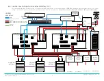
Page 16: ...OAD ROOM ROOM 40 40 CIRCUIT POWER ON AUTO PAIR A B LOAD ROOM ROOM 40 40 20 o OFF 20 o OFF 20 o OFF 20 o OFF CIRCUIT POWER ON AUTO PAIR A B LOAD ROOM ROOM 40 40 CIRCUIT POWER ON AUTO PAIR A B LOAD ROOM ROOM 40 40 20 o OFF 20 o OFF 20 o OFF 20 o OFF Network Switch 1 2 3 4 5 6 7 8 5 VDC To Home Network Panel Bridge Controller UTILITY HOMEGRID BATTERY 1 HOMEGRID BATTERY 2 HOMEGRID BATTERY 3 Smart Cont...

Page 17: ... CIRCUIT POWER ON AUTO PAIR A B LOAD ROOM ROOM 40 40 20 o OFF 20 o OFF 20 o OFF 20 o OFF CIRCUIT POWER ON AUTO PAIR A B LOAD ROOM ROOM 40 40 CIRCUIT POWER ON AUTO PAIR A B LOAD ROOM ROOM 40 40 20 o OFF 20 o OFF 20 o OFF 20 o OFF CIRCUIT POWER ON AUTO PAIR A B LOAD ROOM ROOM 40 40 CIRCUIT POWER ON AUTO PAIR A B LOAD ROOM ROOM 40 40 20 o OFF 20 o OFF 20 o OFF 20 o OFF LINE SIDE TAP GENERATOR GEN ATS...

Page 18: ...MEGRID BATTERY 1 To Gen Start of Gen ATS G N SOL ARK INVERTER 2 MPPT2 MPPT1 GRID GEN LOAD SOL ARK INVERTER 3 MPPT2 MPPT1 GRID GEN LOAD HOMEGRID BATTERY 2 LOAD AC COMBINER LUG IN GUTTER 200A 75A 75A 75A G N GRID COMBINER PANEL PV system designed by others PV INVERTER PV STRING 1 PV INVERTER PV STRING 2 G N PV COMBINER PANEL SIZED PER THE INSTALLED PV SYSTEM PV INVERTER PV STRING 3 1000A DC COMBINER...

Page 19: ...MPPT1 GRID GEN LOAD PV STRING 1 MPPT2 MPPT1 GRID GEN LOAD HOMEGRID BATTERY 2 LOAD AC COMBINER LUG IN GUTTER 200A 75A 75A 75A G N GRID COMBINER PANEL 1000A DC COMBINER AC LINE L1 L2 DC LINE POS NEG WIRE DETAILS LEGEND GEN START STOP GROUND NEUTRAL SOL ARK INVERTER 3 Optional Generator Combiner Electrical Panel Connections IMPORTANT NOTES A 2000A battery combiner busbar is required when connecting m...

Page 20: ...All rights reserved Savant Savant app TrueImage Savant Host Now You Can RacePoint Blueprint Single app Home TrueCommand TrueControl and the Savant logo are trademarks of Savant Systems Inc AirPlay apple AirPort Express AirPort Extreme apple TV apple Remote Desktop FireWire iMac iTunes iPad iPad mini iPad Air iPhone MacBook Mac and OS X are trademarks or trade names of apple Inc iOS is a trademark ...

Reviews: