


Savant Power System Deployment Guide - Sol-Ark
Copyright 2022 Savant Systems, Inc
009-2222-01 | 121222
- 27 -
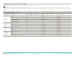
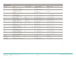
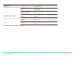
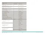
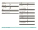
General Settings
Parameter
Sub Level
Savant Settings
Date & Time
Time
hh:mm:ss
Date
day mm/dd/yy
Format
US
Daylight Savings Time
Off
Communication - RS485 Port
(optional Accessory 11BE)
Baud Rate
9600
Device Adress (Dev Addr)
1
Protocol
Modbus
Emulate Grp1
no
Display
Language
English
Contrast
15
Baclight
ON
Volt Label
Vab/bc/ca
Source 1/2
no


